Sheet processing apparatus and image forming apparatus
- Summary
- Abstract
- Description
- Claims
- Application Information
AI Technical Summary
Benefits of technology
Problems solved by technology
Method used
Image

Examples
first embodiment
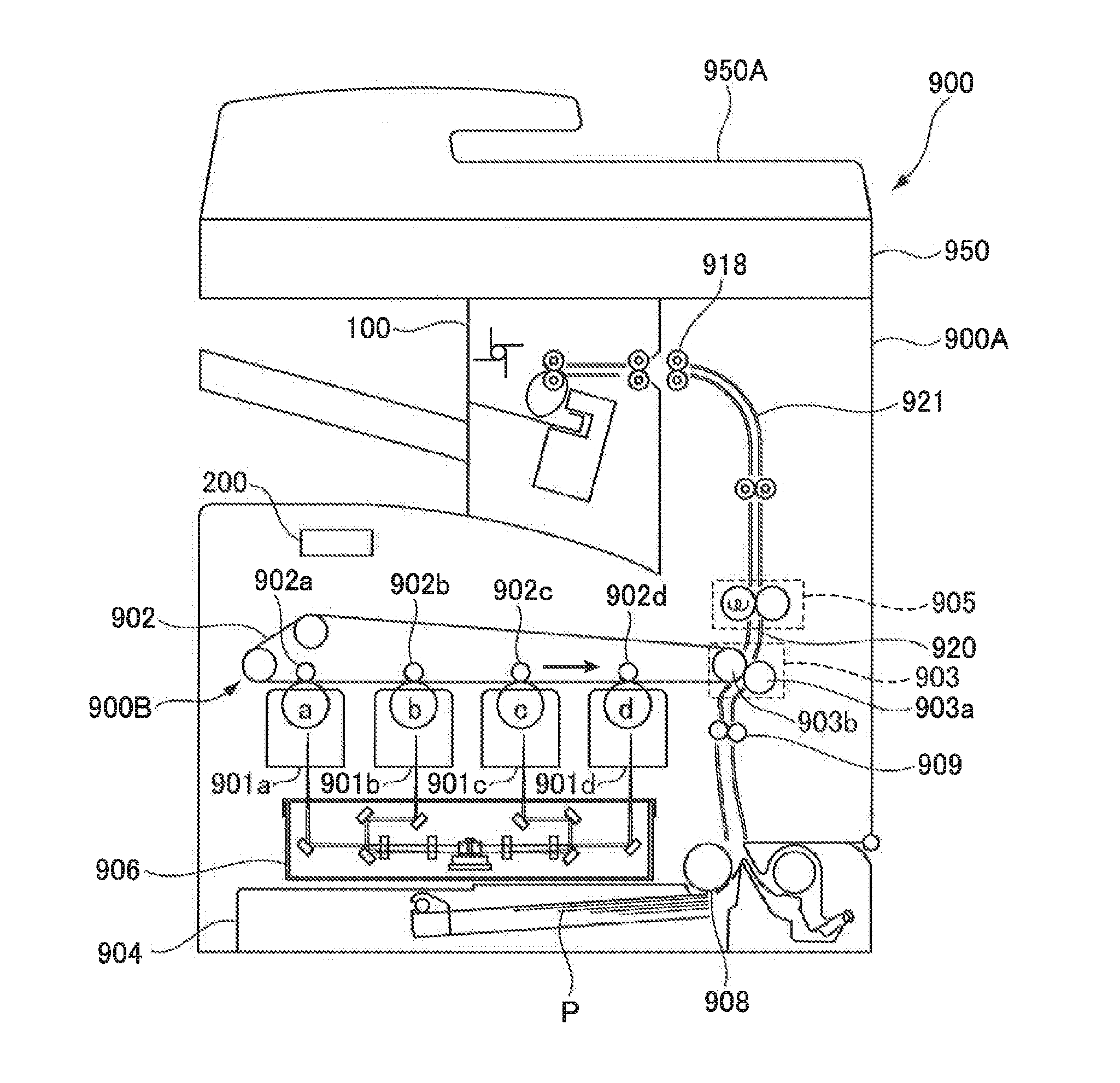
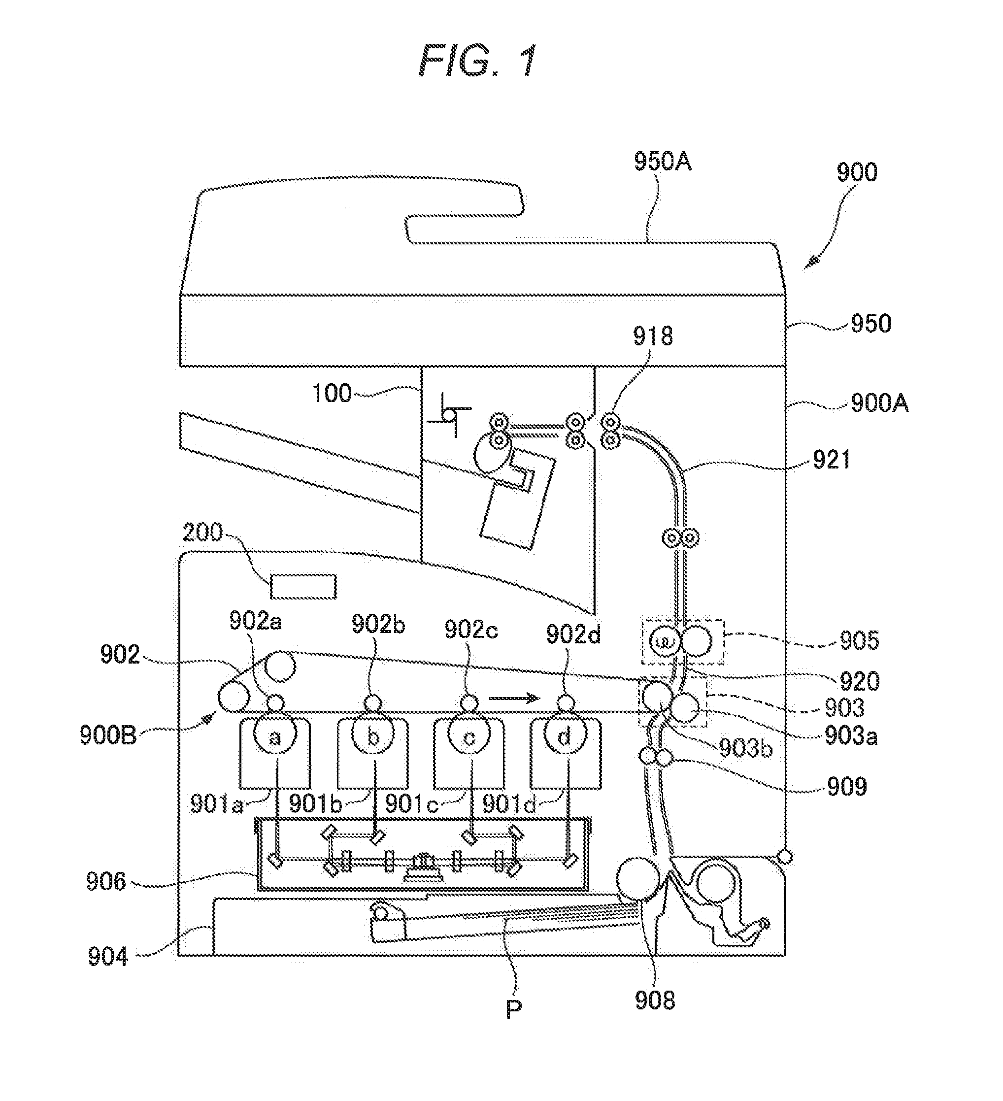
[0033]FIG. 1 is a view illustrating a configuration of an image forming apparatus including a sheet processing apparatus according to the present invention. In FIG. 1, an image forming apparatus 900 includes an image forming apparatus main body (hereinafter referred to as “apparatus main body”) 900A and an image forming portion 900B configured to form an image on a sheet. On the upper portion of the apparatus main body 900A, an image reading apparatus 950 including a document feeder 950A is provided, and a finisher 100 serving as a sheet processing apparatus is arranged between the upper side of the apparatus main body 900A and the image reading apparatus 950.
[0034]In this case, the image forming portion 900B includes photosensitive drums “a” to “d” configured to form toner images of four colors of yellow, magenta, cyan, and black, and an exposure device 906 configured to form electrostatic latent images on the photosensitive drums by emitting laser beams based on image information....
second embodiment
[0091]Next, the present invention will be described, in which the HP of the stapler 110 is set on the far side of the apparatus main body 900A. FIG. 14 is a view illustrating a configuration of a binding portion provided in a finisher serving as a sheet processing apparatus according to this embodiment. Note that, in FIG. 14, the same or corresponding parts are denoted by the same reference symbols as those in FIG. 3 referred to above. In FIG. 14, a staple (STP) HP sensor S247A detects the home position (HP) of the movable stapler 110. The STP HP sensor S247A is provided on the far side of the apparatus main body 900A.
[0092]Then, when user selects the staple job, the finisher control portion 220 drives the STP moving motor M258 to move the stapler 110 from the HP illustrated in FIG. 14 to the near side binding position with respect to the sheet P illustrated in FIG. 12A referred to above. Further, in the case of the far side binding, the stapler 110 is caused to wait at the HP on th...
third embodiment
[0104]Next, the present invention will be described with reference to FIGS. 17A, 17B, and 18 and a flow chart illustrated in FIG. 19. Note that, in FIGS. 17A, 17B, and 18, the same or corresponding parts are denoted by the same reference symbols as those in FIGS. 12A to 12C and 14 referred to above.
[0105]When the job is started, the CPU circuit portion 200 of the image forming apparatus 900 sends, to the finisher control portion 220, information on any one of a job of performing binding of sheets with the staple and a job of performing binding of sheets by staple-less binding. In this case, when the job is a staple job (YES in Step S300), the stapler 110 is moved by the STP moving motor M258 to the near side binding position, the far side binding position, or the two-binding position illustrated in FIGS. 12A, 12B, and 12C referred to above, and caused to wait at the corresponding position.
[0106]Next, after the stapler 110 is moved to the waiting position as described above (Step S30...
PUM
 Abstract
Description
Claims
Application Information
 - Generate Ideas
- Intellectual Property
- Life Sciences
- Materials
- Tech Scout
- Unparalleled Data Quality
- Higher Quality Content
- 60% Fewer Hallucinations
Browse by: Latest US Patents, China's latest patents, Technical Efficacy Thesaurus, Application Domain, Technology Topic, Popular Technical Reports.
© 2025 PatSnap. All rights reserved.Legal|Privacy policy|Modern Slavery Act Transparency Statement|Sitemap|About US| Contact US: help@patsnap.com