Dark current cutoff device and dark current cutoff method

a cutting device and cutting device technology, applied in the direction of electric/fluid circuit, manufacturing tools, transportation and packaging, etc., can solve the problem of not being able to cut off, and achieve the effect of lowering the cutting effect of dark curren

Active Publication Date: 2014-03-20
NISSAN MOTOR CO LTD
View PDF0 Cites 4 Cited by
  • Summary
  • Abstract
  • Description
  • Claims
  • Application Information

AI Technical Summary

Benefits of technology

[0006]Here, among the loads, there is a load that records failure information. That is to say, among the loads, there is a load that determines, as a failure, such a case where the unit concerned is not supplied with electrical power and cannot operate normally, and then records failure information indicating that effect. Here, in a conventional device, in such a case of pulling out the short-circuit pin or the like in order to cut off the dark current, then the load having a function to perform failure recording processing und

Problems solved by technology

Here, in a conventional device, in such a case of pulling out the short-circuit pin or the like in order to cut off the dark current, then the load having a function to perform failure recording processing undesirably performs the failure recording processing since

Method used


Image

  • Dark current cutoff device and dark current cutoff method
  • Dark current cutoff device and dark current cutoff method
  • Dark current cutoff device and dark current cutoff method

Examples


first embodiment

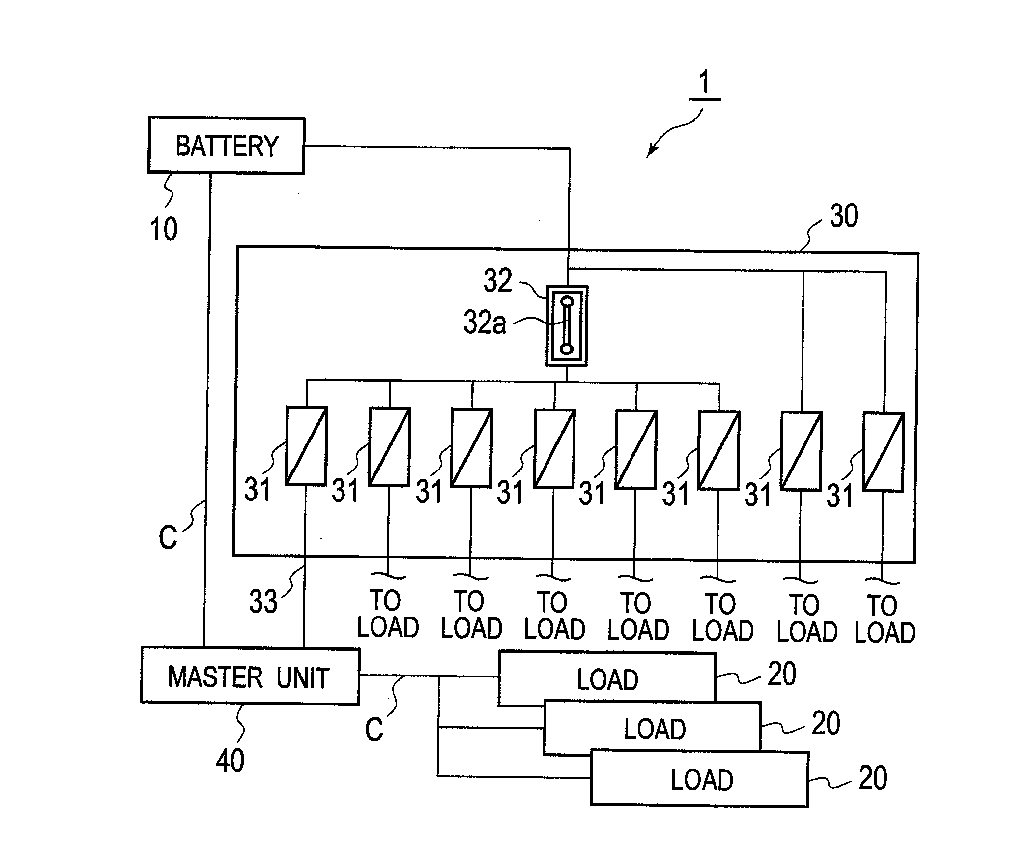
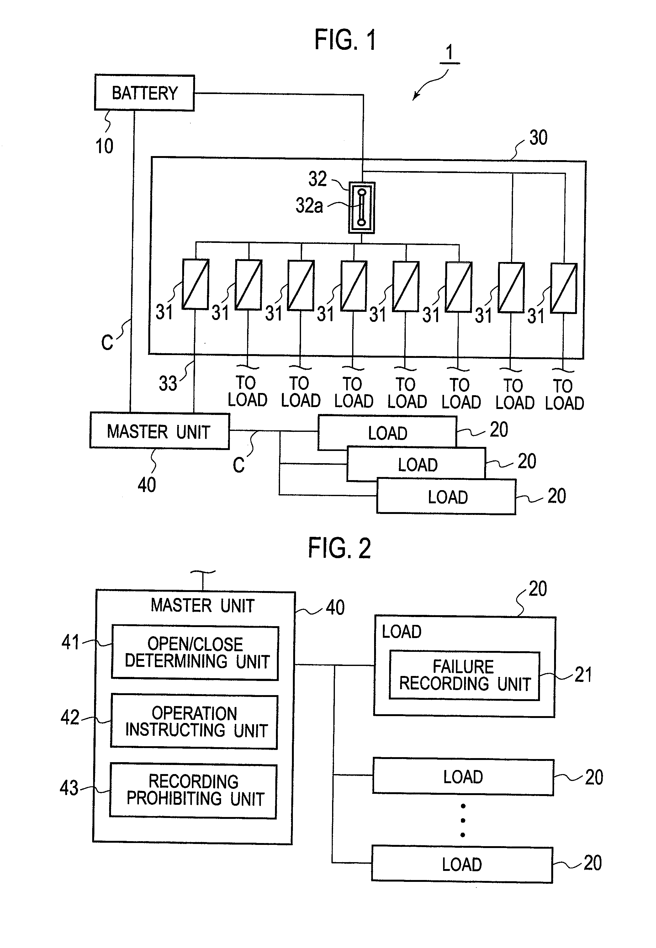
[0016]A description is made of a first embodiment as a preferred embodiment of the present invention based on the drawings. FIG. 1 is a schematic configuration diagram of a dark current cutoff device 1 according to this embodiment. As shown in FIG. 1, a dark current cutoff device 1 is composed of: a battery 10; loads 20; a fuse block 30; and a master unit 40.

[0017]The battery 10 is a unit that supplies electrical power to the loads 20. The loads 20 are a variety of instruments such as meters, which are mounted on a vehicle. Among the loads 20, there are a large number of loads such as an audio instrument, to which it is not necessary to supply the electrical power at the time of transporting and storing the vehicle. The fuse block 30 is a block that includes a large number of fuses 31 which protect the loads 20 from a larger current than a rated current in the case where the larger current concerned flows through the loads 20. Such a current from the battery 10 is supplied through t...

second embodiment

[0034]Specifically, in the second embodiment, in the case where it is determined that the cutoff switch 32 is opened by the open / close determining unit 41, the operation instructing unit 42 transmits, to the load 20, the prohibition signal to the effect of prohibiting the failure recording processing. Moreover, the load 20 includes a recording prohibiting unit 22. Upon receiving the prohibition signal from the operation instructing unit 42, the recording prohibiting unit 22 of the load 20 prohibits the failure information from being recorded by the failure recording unit 21 as a result that it is determined thereby that there is a failure. That is to say, the recording prohibiting unit 22 masks such a function of the failure recording processing by the failure recording unit 21.

[0035]Moreover, in the second embodiment, the master unit 40 includes an abnormality detecting unit 44 in place of the recording prohibiting unit 43. The abnormality detecting unit 44 the recording prohibitin...


PUM

PropertyMeasurementUnit
Poweraaaaaaaaaa

Abstract

A dark current cutoff device (1) includes: a battery (10) configure to perform electrical power supply to a load (20); a cutoff switch (32), which is provided between the battery (10) and the load (20), cuts off the electrical power supply to the load (20) at a time of being opened, and supplies electrical power to the load (20) at a time of being closed; a failure recording unit (21) that determines and records a case where the load (20) does not operate as a failure of the load (20); and an open/close determining unit (41) that determines that the cutoff switch (32) is opened; and a recording prohibiting unit (22) configure to prohibit, in a case where the cutoff switch (32) is determined to be opened by the open/close determining unit (41), the failure recording unit (21) from determining and recording the failure.

Description

TECHNICAL FIELD[0001]The present invention relates to a dark current cutoff device and a dark current cutoff method.BACKGROUND ART[0002]In recent years, electrical components have tended to be increased in a vehicle, and a dark current has tended to be increased during transportation and storage of the vehicle. Accordingly, in order to prevent a battery from running out during the transportation and storage of the vehicle, there has been proposed a technology for leaving a short-circuit pin or the like of a fuse, which is provided between loads and the battery, in a state of being pulled out (for example, refer to Patent Literatures 1 and 2). Moreover, a device has been proposed, in which a relay is provided between the loads and the battery, and this relay is opened (for example, refer to Patent Literature 3).CITATION LIST Patent Literature [0003][PTL 1] Japanese Patent Laid-Open Publication No. 2008-126812[0004][PTL 2] Japanese Patent Laid-Open Publication No. 2008-179221[0005][PT...

Claims


Application Information

Patent Timeline
IPC IPC(8): H02J7/00
CPCH02J7/0063B60R16/03B60R16/033
Inventor NOBUSAWA, HISASHIKUBOTA, AYUMUAKAHO, HIROMASA
Owner NISSAN MOTOR CO LTD
Why Eureka
Try Eureka