A self-excited pump driven by two oscillators

A dual vibrator and vibrator technology, applied to pumps with flexible working elements, pumps, machines/engines, etc., can solve the problem of low output flow and pressure accuracy, poor flatness and cut-off effect, pump output flow and pressure drop, etc. problem, to achieve the effect of improving output capability and control accuracy, good cut-off effect, and high output efficiency

Active Publication Date: 2020-08-18
ZHEJIANG NORMAL UNIVERSITY
View PDF8 Cites 0 Cited by
  • Summary
  • Abstract
  • Description
  • Claims
  • Application Information

AI Technical Summary

Problems solved by technology

However, in actual work, the output flow and pressure of the piezoelectric pump are greatly affected by the working conditions. The fluid viscosity, temperature and output pressure affect the resonant frequency of the pump by affecting the system damping. When the deviation of the set excitation frequency is large, the output flow and pressure of the pump will drop significantly
Therefore, the output performance of the piezoelectric pump at a fixed frequency is not ideal, and the accuracy of the output flow and pressure calculated according to the set driving voltage and frequency is also low
In addition, most of the existing piezoelectric pumps use cantilever beam stop valves, which have low rebound stiffness, poor flatness and cut-off effect, which seriously affect the output flow and pressure of the pump.

Method used


Image

  • A self-excited pump driven by two oscillators
  • A self-excited pump driven by two oscillators
  • A self-excited pump driven by two oscillators

Examples


Embodiment Construction

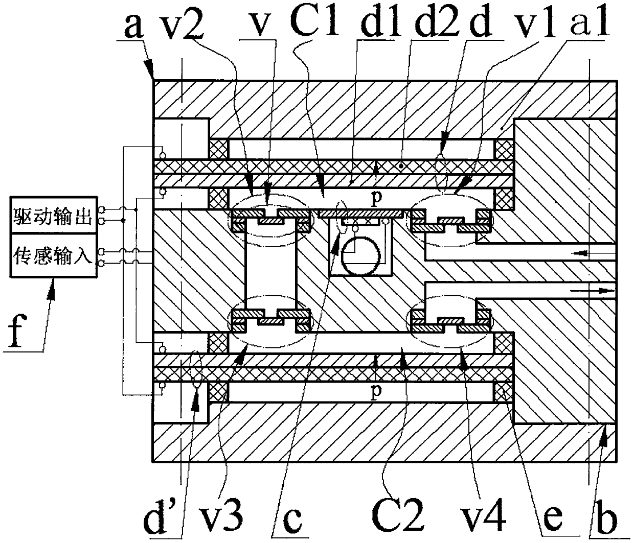
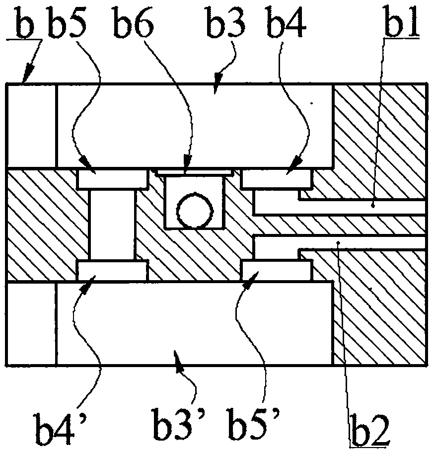
[0017] A self-excited pump driven by double oscillators of the present invention is composed of pump cover a, pump body b, disc valve v, sensor c, upper chamber oscillator d, lower chamber oscillator d', sealing ring e, power supply f and wire group . The pump body b is provided with an inlet b1, an outlet b2, an upper body cavity b3 and a lower body cavity b3', the bottom wall of the upper body cavity b3 is provided with an upper inlet valve cavity b4 and an upper outlet valve cavity b5, and the top wall of the lower body cavity b3' The lower inlet valve cavity b4' and the lower outlet valve cavity b5' are provided, the side walls of the upper body cavity b3 and the lower body cavity b3' are provided with wiring grooves, the bottom wall of the upper body cavity b3 or the top wall of the lower body cavity b3' There is a sensor chamber b6 on the top, and a wiring hole is provided on the side wall of the sensor chamber b6; the upper inlet valve chamber b4 communicates with the i...


PUM


Abstract

The invention belongs to the field of micro-fluid transmission and control, and particularly relates to a self-excitation pump driven by a double-vibrator. A sensor is arranged in the pump body, an upper inlet valve cavity and a lower outlet valve cavity of the pump body and disc-shaped valves adhered to the upper inlet valve cavity and the lower outlet valve cavity form an upper inlet valve and alower outlet valve respectively, the disc-shaped valve is formed by bonding a pressing ring, a valve plate and a valve seat, pump covers are arranged on the upper side and the lower side of the pumpbody. the pump cover presses the upper cavity vibrator and lower cavity vibrator into the upper cavity and the lower cavity of the pump body respectively through the sealing ring. the upper cavity vibrator and the lower cavity vibrator are formed by bonding a substrate sheet and a piezoelectric sheet, and the sensor and the upper cavity vibrator and the lower cavity vibrator are connected with a power source through different wire sets, an upper cavity vibrator, a lower cavity vibrator, a sealing ring, an upper inlet valve and a lower outlet valve to form an upper pump cavity and a lower pumpcavity which are connected in series, the power supply outputs a direct-current voltage signal, and when the fluid pressure reaches an extreme value, the output voltage of the power supply and the deformation direction of the upper cavity and the lower cavity are reversed. The self-excitation pump has the advantages that the excitation frequency is automatically formed according to the fluid pressure change state of the pump cavity, the efficiency of the valve is high, the output capability and the control precision are high.

Description

technical field [0001] The invention belongs to the field of microfluid transmission and control, in particular to a self-excited pump driven by double vibrators. Background technique [0002] As an important branch of piezoelectric actuators, piezoelectric pumps have the advantages of simple structure, small size, fast response, no electromagnetic interference, easy operation, and good flow / pressure controllability. And fuel cell fuel supply, micro-electro-hydraulic systems and other aspects have broad application prospects, and its research and development has attracted extensive attention from scholars all over the world. In order to meet the application requirements in different fields, piezoelectric pumps with various structures have been proposed. Although the structure and performance of the proposed piezoelectric pumps are quite different, they all use the bending deformation of the wafer-shaped piezoelectric vibrator under the action of an electric field to realize...

Claims


Application Information

Patent Timeline
Patent Type & Authority Patents(China)
IPC IPC(8): F04B43/04
Inventor 蒋永华柴超辉王淑云郑佳佳梁程程光明
Owner ZHEJIANG NORMAL UNIVERSITY
Why Eureka
Try Eureka