Organic Light Emitting Display

a light-emitting display and organic technology, applied in the field of organic light-emitting displays, can solve the problems of difficult process for forming organic light-emitting displays, difficult realization of thin and flexible organic light-emitting displays, increased hardness and thickness, etc., and achieve the effect of preventing permeation of moistur

Active Publication Date: 2014-03-20
LG DISPLAY CO LTD
View PDF11 Cites 36 Cited by
  • Summary
  • Abstract
  • Description
  • Claims
  • Application Information

AI Technical Summary

Benefits of technology

[0020]An object of the present invention is to provide an organic light emitting display that can efficiently prevent permeation of moisture in a structure including an in-cell touch electrode array.

Problems solved by technology

First, in a case in which an organic light emitting display panel and a touchscreen are independently formed and the touchscreen is then attached to the organic light emitting display panel, the organic light emitting display panel and the touchscreen require separate glasses, thus causing increase in hardness and thickness, which makes realization of thin and flexible organic light emitting displays impossible.
Second, the organic light emitting display panel and the touchscreen have different panel shapes, thus making processes for forming these components complicated and thus decreasing yield and price competiveness.
Third, a polarizing plate is provided in order to prevent recognition of exterior light of the organic light emitting display panel. The polarizing plate has a thickness of about 150 μm or more, is expensive and causes a deterioration in transmittance. Accordingly, since the polarizing plate deteriorates flexibility when used for displays and is expensive, other alternative capable of preventing deterioration in visibility is required.

Method used


Image

  • Organic Light Emitting Display
  • Organic Light Emitting Display
  • Organic Light Emitting Display

Examples


first embodiment

[0084]FIG. 5 is a plan view illustrating the present invention. FIG. 6 is a sectional view taken along the line II-II′ of FIG. 5. FIG. 7 is a sectional view taken along the line III-III′ of FIG. 3.

[0085]As shown in FIGS. 5 to 7, a structure of the second buffer layer 220 according to the first embodiment of the present invention will be described.

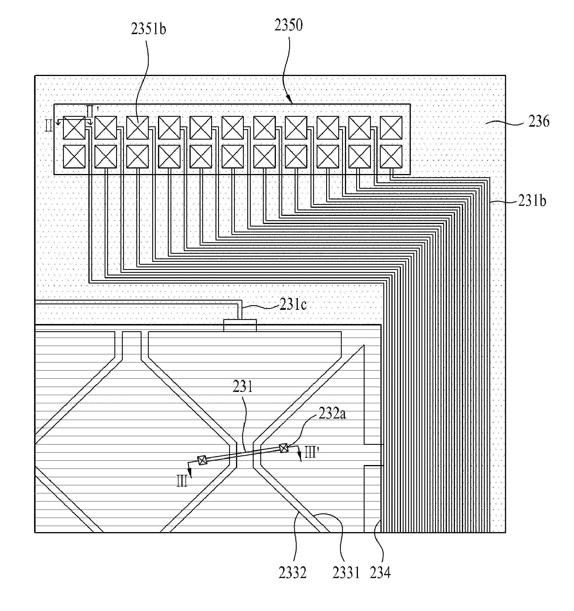
[0086]As shown in FIG. 5, the second buffer layer 220 includes an active region where a first electrode 2331 and a second electrode 2332 sensing touch intersect each other, and a dead region disposed out of the active region.

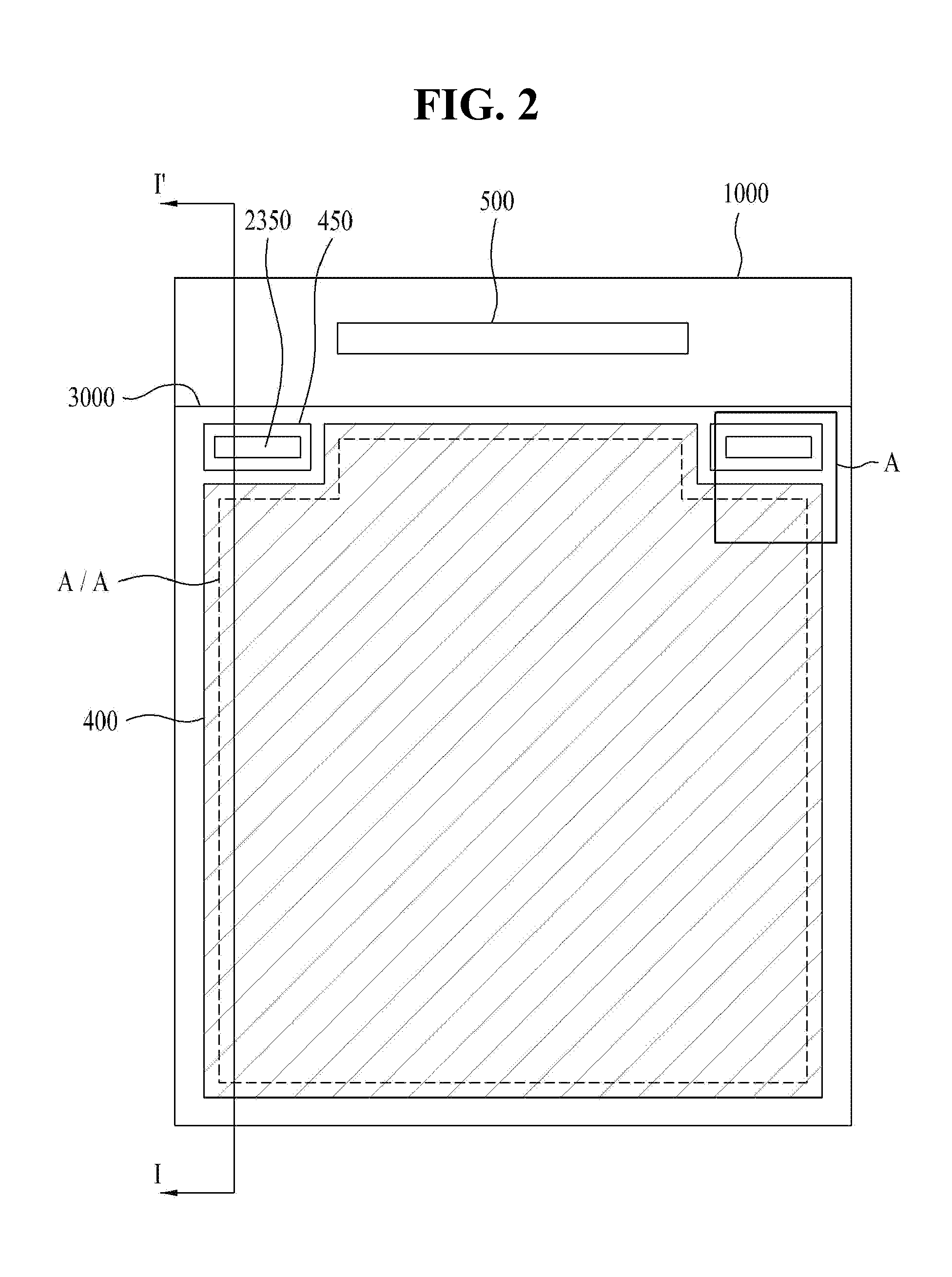
[0087]Here, a touch pad portion including a plurality of touch pads 2351b spaced from one another is defined in a part of the dead region of the second buffer layer 220. As shown in FIG. 2, the touch pad portion 2350 is disposed at both edges of the second buffer layer 220.

[0088]Also, in the dead region, the ends of the first electrode 2331 and the second electrode 2332 are connected through routing lines 231b and 231c ...

second embodiment

[0098]FIG. 8 is a plan view illustrating the present invention. FIG. 9 is a sectional view taken along the line IV-IV′ of FIG. 8.

[0099]As shown in FIGS. 8 and 9, the second buffer layer of the organic light emitting display according to the second embodiment of the present invention has the same structure as that of the first embodiment in that the third interlayer insulating film is formed in the touch pad and the surroundings thereof (third interlayer insulating film is not formed in the active region).

[0100]In this case, since the edge of the sealant 450 directly contacts the third interlayer insulating film 236 formed of an inorganic film material, the inorganic film material capable of serving as a barrier against foreign matter such as moisture is present at the edge of the sealant 45 and contact characteristics of the touch pad can thus be stably maintained even after environmental reliability testing which is performed by exposing the touch pad for a long period of time unde...

third embodiment

[0102]FIG. 10 is a plan view illustrating the present invention. FIG. 11 is a sectional view taken along the line V-V′ of FIG. 10.

[0103]As shown in FIGS. 10 and 11, in the third embodiment of the present invention, the upper layers of the touch pad correspond to transparent conductive films 233 and 235 and the uppermost layers of the second buffer layer 220 that contact the edge of the sealant 450 correspond to the transparent conductive films 233 and 235. In this case, a plurality of touch pads 2351b in the touch pad portion 2350 are isolated through spaced transparent conductive films 233 and 235, the transparent conductive films 233A and 235A are formed in the dead region disposed outside of the touch pad portion 2350, and the surface that contacts the sealant 450 and the surface of the exposed dead region correspond to transparent conductive films in regions excluding the touch pads, thus preventing effects of moisture and exterior air on the interlayer insulating film of the to...


PUM


Abstract

Disclosed is an organic light emitting display an organic light emitting display that can efficiently prevent permeation of moisture in a structure including an in-cell touch electrode array, the uppermost layer of the second buffer layer contacting the sealant between the dead region adjacent to the touch pad portion and the touch pads is an inorganic film.

Description

[0001]This application claims the benefit of Korean Patent Application No. 10-2012-0103189, filed on Sep. 18, 2012, which is hereby incorporated by reference as if fully set forth herein.BACKGROUND OF THE INVENTION[0002]1. Field of the Invention[0003]The present invention relates to an organic light emitting display, and more particularly, to an organic light emitting display that can efficiently prevent permeation of moisture in a structure including an in-cell touch electrode array.[0004]2. Discussion of the Related Art[0005]Examples of flat panel displays include liquid crystal displays (LCDs), organic light emitting displays (OLEDs), plasma display panels (PDPs), quantum dot panels (PDPs), field emission displays (FEDs), electrophoretic displays (EPDs) and the like. These displays include a flat display panel realizing an image in common as an essential component. Such a flat display panel has a configuration in which a pair of transparent insulating substrates are joined togeth...

Claims


Application Information

Patent Timeline
Patent Type & Authority Applications(United States)
IPC IPC(8): G06F3/041
CPCG06F3/041G06F3/0412G06F3/04164G06F3/0446G06F3/0443H10K59/88H10K59/40H10K59/131H10K50/8426G06F3/0416B32B2457/206
Inventor CHOI, HO-WON
Owner LG DISPLAY CO LTD
Why Eureka
Try Eureka