
Heat Sink Rail System

a rail system and heat sink technology, applied in the direction of weapons, butts, weapon components, etc., can solve the problems of shortening the effective life of the barrel, affecting so as to reduce the impact of the shooter's grip on the accuracy of the firearm, the effect of dispersing heat within the rail system

Inactive Publication Date: 2014-03-27
LEE SHANYAO
View PDF1 Cites 36 Cited by
  • Summary
  • Abstract
  • Description
  • Claims
  • Application Information

AI Technical Summary

Benefits of technology

The present invention is about a way to cool down a firearm rail system to prevent the gun from getting too hot. The technical effect of this innovation is to improve the reliability and performance of firearms by preventing malfunctions caused by overheating.

Problems solved by technology

Though wearing gloves or other protection can keep the shooter's hands safe from the issues of overheating that accompany present embodiments of the prior art, the excessive heat will transfer to the accessories on the rail and cause failure on the electronic components.
This method can cause the barrel to overheat, which will shorten the barrel's effective life, make the weapon less accurate and reliable in its shooting and may cause dangerous cook-off (projectile fires automatically).
This method is useful in preventing the user from hurting himself or herself, but does not cool the barrel itself and can in some cases cause more rapid overheating of the barrel.
Cooling the barrel is as important if not more important than protecting the shooter's hand from painful heat because overheating the barrel will shorten the barrel's effective life, make the weapon less accurate and reliable in its shooting and may cause dangerous cook-off (projectile fires automatically).
If the shooter grasps the rail system which is firmly attached to the barrel at both ends, the shooter's grip will affect the firing of the firearm negatively, therefore reducing accuracy or potentially damaging the barrel.

Method used


Image

  • Heat Sink Rail System
  • Heat Sink Rail System
  • Heat Sink Rail System

Examples


Embodiment Construction

FIGS. 1, 7

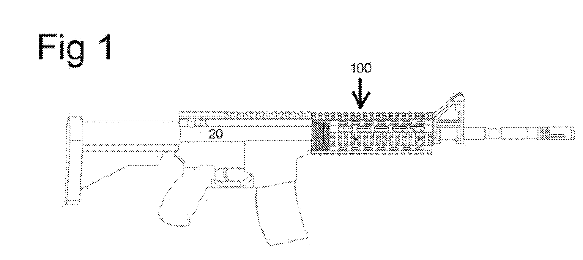
[0026]With reference now to the drawings, the preferred embodiment of the heat sink rail system according the present invention is herein described. As can be seen in FIG. 1, according to certain embodiments of the prior art, the rail system 100 is situated around barrel 11 of the firearm 20. Rail system 10 contains holes for air to pass through. Rail system 100 allows shooter to grip firearm at a distance from barrel 11 such that heat from barrel 11 does not fully reach shooter's grip.

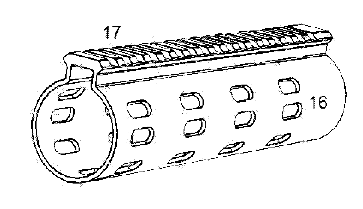
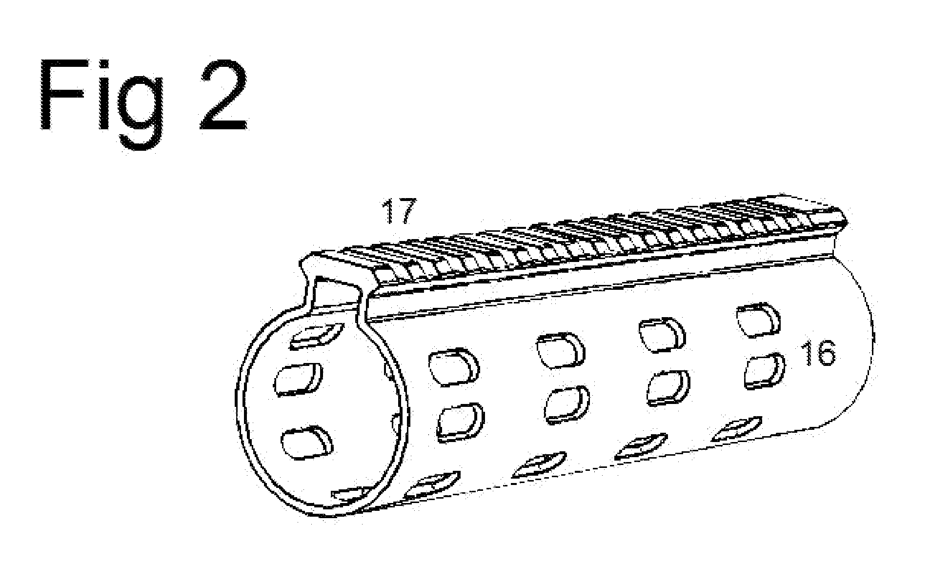
[0027]As can be seen in FIG. 7, according to certain embodiments of the present invention, rail system 10 is situated around barrel 11 of firearm 20. Fins 12 extend inwards from inner layer of cooling system 13. Inner layer of cooling system 13 is circumscribed by o-rings 14, made, in certain embodiments of the present invention, of non-conducting material, which are circumscribed by outer layer of cooling system 15. Outer layer of cooling system 15 is circumscribed by rail cover 16. Railing...


PUM


Abstract

A method and apparatus providing for a rail system which further acts to cool a firearm. Wherein said cooling process acts by the passage of air through fins of the apparatus. Whereby said method and apparatus provides for a cooling mechanism which does not inhibit the firearm from attaching accessories.

Description

BACKGROUND OF THE INVENTION[0001]1. Field of the Invention[0002]The application relates to a method and apparatus for a handguard rail system on a firearm with heat dissipating qualities.[0003]2. Prior Art[0004]Presently, most modern automatic small projectile weapons, including machine guns, rifles, and sub-machine guns, use a handguard made of aluminum or other metals with standard picatinny rails in order to mount rifle accessories, such as a flash light, scope, red dot, laser, vertical grip and others.[0005]Though these rails are convenient for mounts and attachments, these Aluminum and metal constructed handguards conduct heat which transfers from the barrel, chamber and gas block to the hand of the shooter quickly, as aluminum and other metals have superior heat conducting ability. To prevent pain or burning during use, shooters must wear gloves or other protection. Though wearing gloves or other protection can keep the shooter's hands safe from the issues of overheating that ...

Claims


Application Information

Patent Timeline
IPC IPC(8): F41A21/44
CPCF41A21/44F41A21/24F41C23/16
Inventor LEE, SHANYAO
Owner LEE SHANYAO
Learn More