Active steering windrow shields

a windrow shield and active technology, applied in the field of harvesting machines, can solve the problems of poor feed performance, pickup assembly plugging, and system not being able to effectively direct the windrow to the towed implement during turns or side hills,

Inactive Publication Date: 2014-03-27
CNH IND AMERICA LLC
View PDF12 Cites 23 Cited by
  • Summary
  • Abstract
  • Description
  • Claims
  • Application Information

AI Technical Summary

Benefits of technology

[0005]Accordingly, the present invention, in any of the embodiments described herein, may provide one or more of the following advantages:
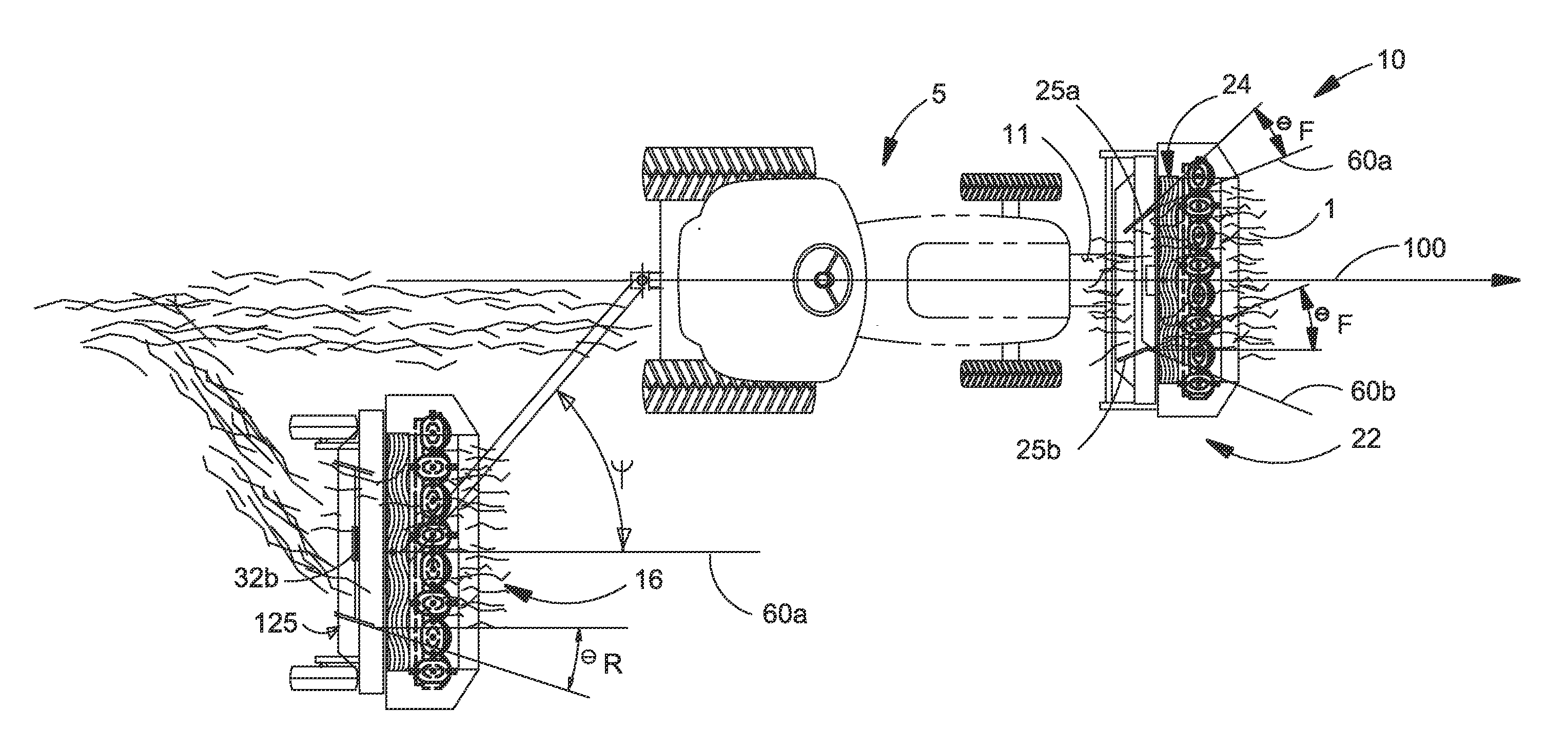
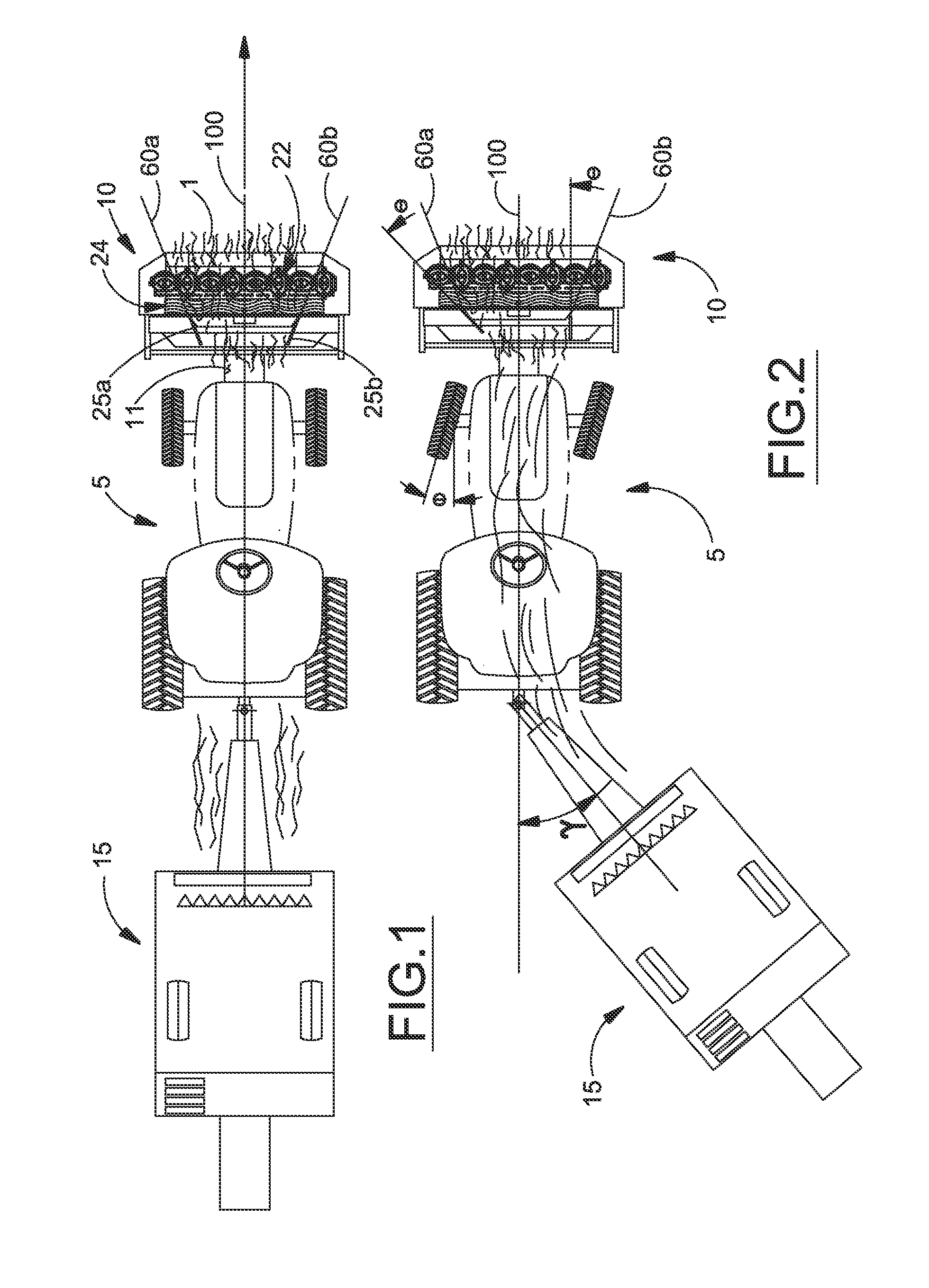
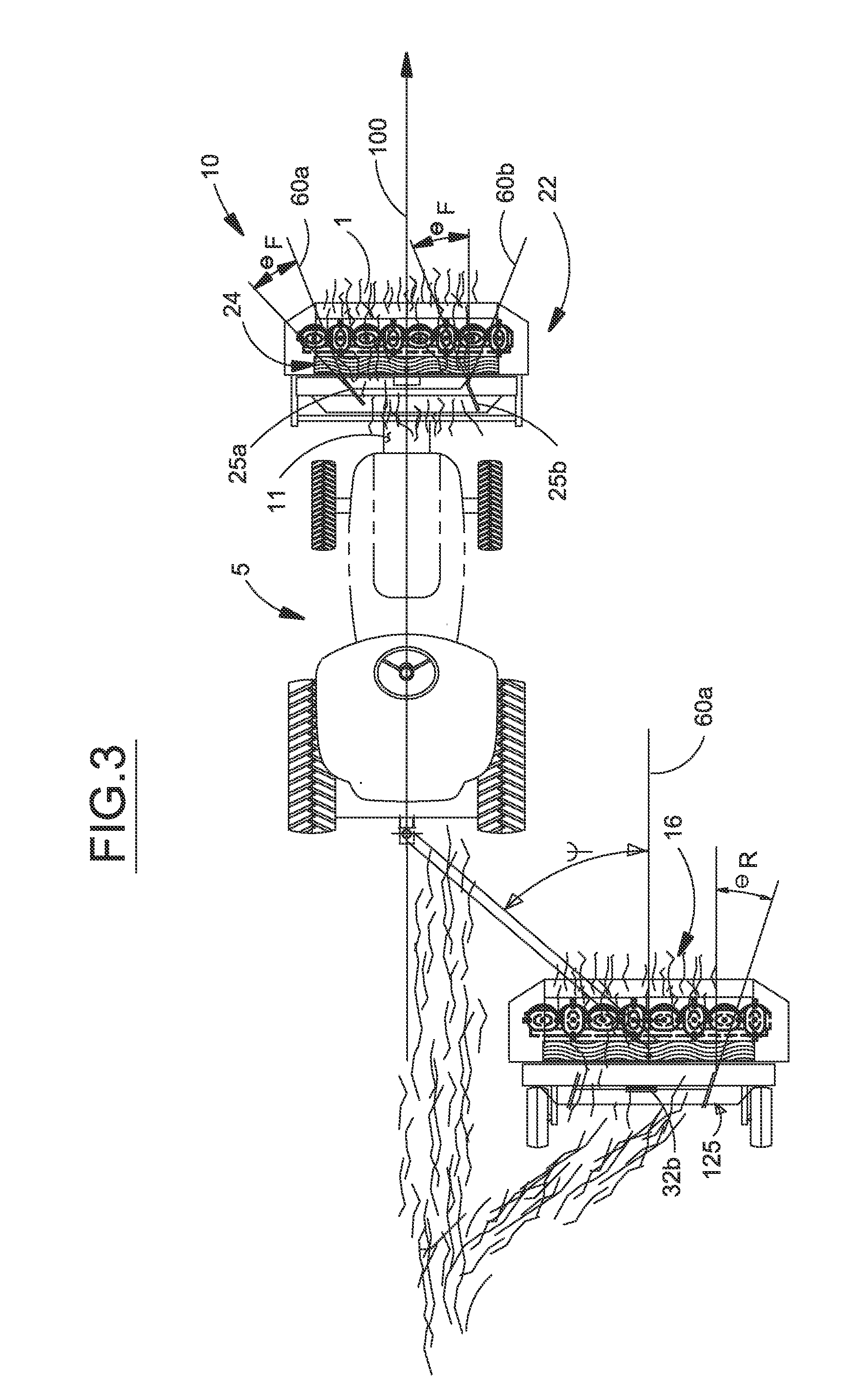
[0006]It is an object of the present invention to provide a steering mechanism for windrow guide shields on an agricultural mower that enables lateral deflection of the crop discharge stream to be selectively altered during machine operation.
[0008]It is another object of the present invention to provide a steering mechanism for windrow guides on a forward-mounted agricultural mower operated in conjunction with a towed agricultural implement having a crop pickup wherein the steering mechanism allows the crop windrow to be positioned for pickup by the towed implement as the machine traverses uneven terrain, such as a side hill.
[0009]It is a further object of the present invention to provide a steering mechanism for windrow guides on an agricultural mower that enables lateral deflection of the crop discharge stream on a forwardly mounted mower operated in conjunction with a towed center-pivot mower also equipped with said steering mechanism to eliminate the need for a separate crop windrow merger apparatus.
[0010]It is a still further object of the present invention to provide a steering mechanism for positioning adjustable crop guides on an agricultural mower that is durable in construction, inexpensive of manufacture, carefree of maintenance, easily assembled, and simple and effective to use.

Problems solved by technology

While feeding of mowed crop to the towed implement is normally centered during straight, flat operation, the system cannot effectively direct the cut crop windrow to the towed implement during turns or on side hills.
Misalignment of the windrow and the towed implement pickup assembly causes cut crop to be left in the field and / or uneven feeding resulting in pickup assembly plugging, poor feed performance, or misshapen bales.
Such arrangements to not typically allow for on-the-fly adjustment of the shields in response to changing tractor-implement alignments.

Method used


Image

  • Active steering windrow shields
  • Active steering windrow shields
  • Active steering windrow shields

Examples


Embodiment Construction

)

[0018]Many of the fastening, connection, processes and other means and components utilized in this invention are widely known and used in the field of the invention described, and their exact nature or type is not necessary for an understanding and use of the invention by a person skilled in the art, and they will not therefore be discussed in significant detail. Also, any reference herein to the terms “left” or “right” are used as a matter of mere convenience, and are determined by standing at the rear of the machine facing in its normal direction of travel. Likewise, “forward” and “rearward” are determined by the normal direction of travel. “Upward” and “downward” orientations are relative to the ground or operating surface as are any references to “horizontal” or “vertical” planes. Furthermore, the various components shown or described herein for any specific application of this invention can be varied or altered as anticipated by this invention and the practice of a specific ap...


PUM


Abstract

A system for positioning crop windrow guide shields projecting generally rearwardly alongside the crop discharge stream as it exits an agricultural mower. The shields are coupled for simultaneous, coordinated movement and repositioned by a powered actuator in response to either a manual input by a vehicle operator or automatically by a controller based on a steering angle deflection between a tractor and a towed implement. The system may be adapted for use with a single implement being operated on a side hill to control windrow drifting. The system may also be used with simultaneously operated front-mounted and pull-behind mowers to direct the crop discharge streams into a merged windrow.

Description

BACKGROUND OF THE INVENTION[0001]This invention relates generally to harvesting machines, such as mowers, of the type having guide panels to influence the trajectory of the crop material being discharged from the mower, and, more particularly, to a system for automatically repositioning the crop guide panels to ideally place a crop windrow for engagement by a trailing implement even as the harvesting machine traverses a non-straight path.[0002]Single pass harvesting operations often involve mounting a mower on the front hitch of a tractor and towing a baler or other implement behind the tractor where it engages the cut crop windrow deposited on the ground by the mower. While feeding of mowed crop to the towed implement is normally centered during straight, flat operation, the system cannot effectively direct the cut crop windrow to the towed implement during turns or on side hills. The forward mounted and towed implements track on different turning radii as the vehicle is turned and...

Claims


Application Information

Patent Timeline
Patent Type & Authority Applications(United States)
IPC IPC(8): A01D43/00
CPCA01D34/667A01D43/006A01D57/28A01D34/664A01D45/00A01D2101/00
Inventor FAY, II, JEFFREY
Owner CNH IND AMERICA LLC
Why Eureka
Try Eureka