Magnetic-Latch Stabbing Guide

a magnetic latch and stabbing guide technology, which is applied in the direction of drilling casings, drilling pipes, and accessories for wellbores/wells, etc., can solve the problems of affecting the use the hinges the latching mechanism located on the outer surface of the stabbing guide, so as to achieve the effect of convenient use, quick and effective use, and safe operation

Inactive Publication Date: 2014-03-27
MINER DANIEL PETE
View PDF8 Cites 9 Cited by
  • Summary
  • Abstract
  • Description
  • Claims
  • Application Information

AI Technical Summary

Benefits of technology

[0011]Benefits and advantages of the present invention include, but are not limited to, providing a magnetic-latch stabbing guide apparatus, which guides drill pipes together for connection in a safe, quick and effective manner. The magnetic-latch stabbing guide is

Problems solved by technology

Often the stabbing guide's hinges, located on the outer surface, become unusable due to the action of rust, ice or mud build up, and routine wear.
Similarly, the latching mechanism, also located on the outer surface of the guide, becomes damaged through repetitive use, rust and ice and mud build-up.
If the currently-used stabbing guides are not mechanically unlatched during the connection process,

Method used


Image

  • Magnetic-Latch Stabbing Guide
  • Magnetic-Latch Stabbing Guide
  • Magnetic-Latch Stabbing Guide

Examples


Embodiment Construction

[0016]Reference will now be made in detail to embodiments of the invention, examples of which are illustrated in the accompanying drawings. Throughout the following detailed description, the same reference characters refer to the same or similar elements in all figures.

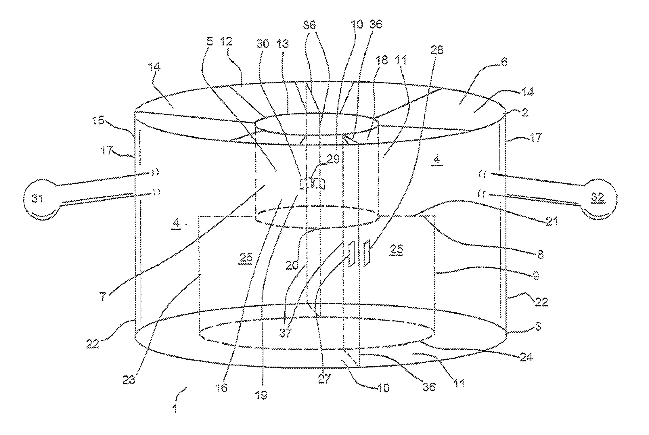
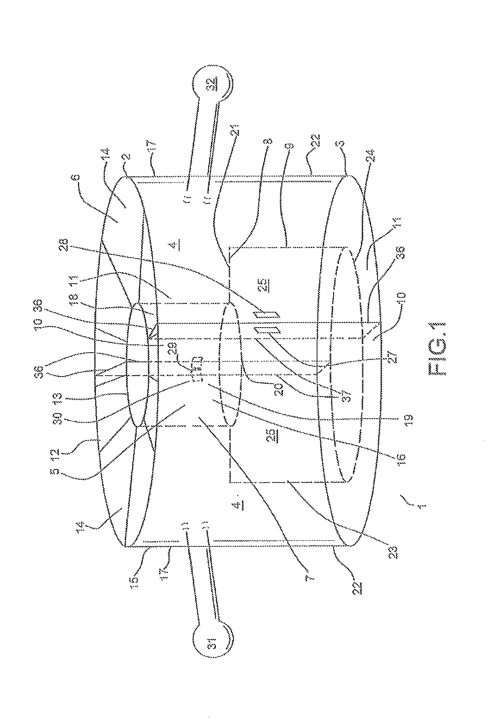
[0017]FIG. 1 depicts a perspective view of the front of one embodiment of the present invention showing the magnetic-latch stabbing guide 1 in closed position. In one embodiment and as shown in FIG. 1, the magnetic-latch stabbing guide 1 comprises a cylindrical apparatus having a top portion 2 and bottom portion 3. At the guide top portion 2, a funnel-shaped portion 6 is shown. The funnel-shaped portion has a large opening 12 disposed at the very top of the funnel-shaped portion 6. The funnel-shaped portion inner surface 14 connects the large funnel-shaped portion opening 12 to a smaller funnel-shaped portion opening 13. The magnetic-latch stabbing guide 1 further comprises a funnel-shaped portion outer surface 15 on ...


PUM


Abstract

A magnetic-latch stabbing guide apparatus is presented enabling a first drill pipe to connect with a second drill pipe. The magnetic-latch stabbing guide easily attached to the first drill pipe and facilitates connection between the first drill pipe and the second drill pipe. During the connection process, the magnetic-latch stabbing guide easily detaches from the two drill pipes without physical manipulation of the magnetic-latch stabbing guide.

Description

FIELD OF THE INVENTION[0001]The invention comprises a stabbing guide apparatus that facilitates connection of a first drill pipe to a second drill pipe. Specifically, the apparatus provides an internal coupling region which enables the male and female ends of a drill pipe to form a connection without damaging the ends of the drill pipe. The apparatus easily attaches to the first drill pipe, guides a second drill pipe into a position for attachment to the first drill pipe and easily detaches from two drill pipes after the first and second drill pipes form a connection.BACKGROUND OF THE INVENTION[0002]Drill pipe extends down into oil and gas formation beneath an oil or gas drilling rig floor. Drill pipe provides a conduit for the flow of oil or gas from an oil or gas formation well below the rig floor to a collection device. To achieve sufficient depth of drill pipe into a formation, drill pipes are connected together as they are lowered into a formation. Effective and strong drill pi...

Claims


Application Information

Patent Timeline
IPC IPC(8): E21B19/24
CPCE21B19/24
Inventor MINER, DANIEL PETE
Owner MINER DANIEL PETE
Why Eureka
Try Eureka