Video image display system and head mounted display

a display system and display technology, applied in static indicating devices, instruments, optical elements, etc., can solve the problem of not considering the use of transmissive head mounted displays that allow visual recognition of an outside scen

Inactive Publication Date: 2014-03-27
SEIKO EPSON CORP
View PDF7 Cites 119 Cited by
  • Summary
  • Abstract
  • Description
  • Claims
  • Application Information

AI Technical Summary

Benefits of technology

[0021]The invention can be implemented in a variety of aspects in addition to the video image display system. For example, the invention can be implemented in the form of a head mounted display, an information app

Problems solved by technology

For example, in the video image display system of related art described above, to select one set of video images from the multiple sets of video images and display the selected video images in any of the head mounted displays, the user needs to perform operation of selecting the one set of video images, which is cumbersome in some cases.
Further, in the video image display system of related described above,

Method used


Image

  • Video image display system and head mounted display
  • Video image display system and head mounted display
  • Video image display system and head mounted display

Examples


first embodiment

A. First Embodiment

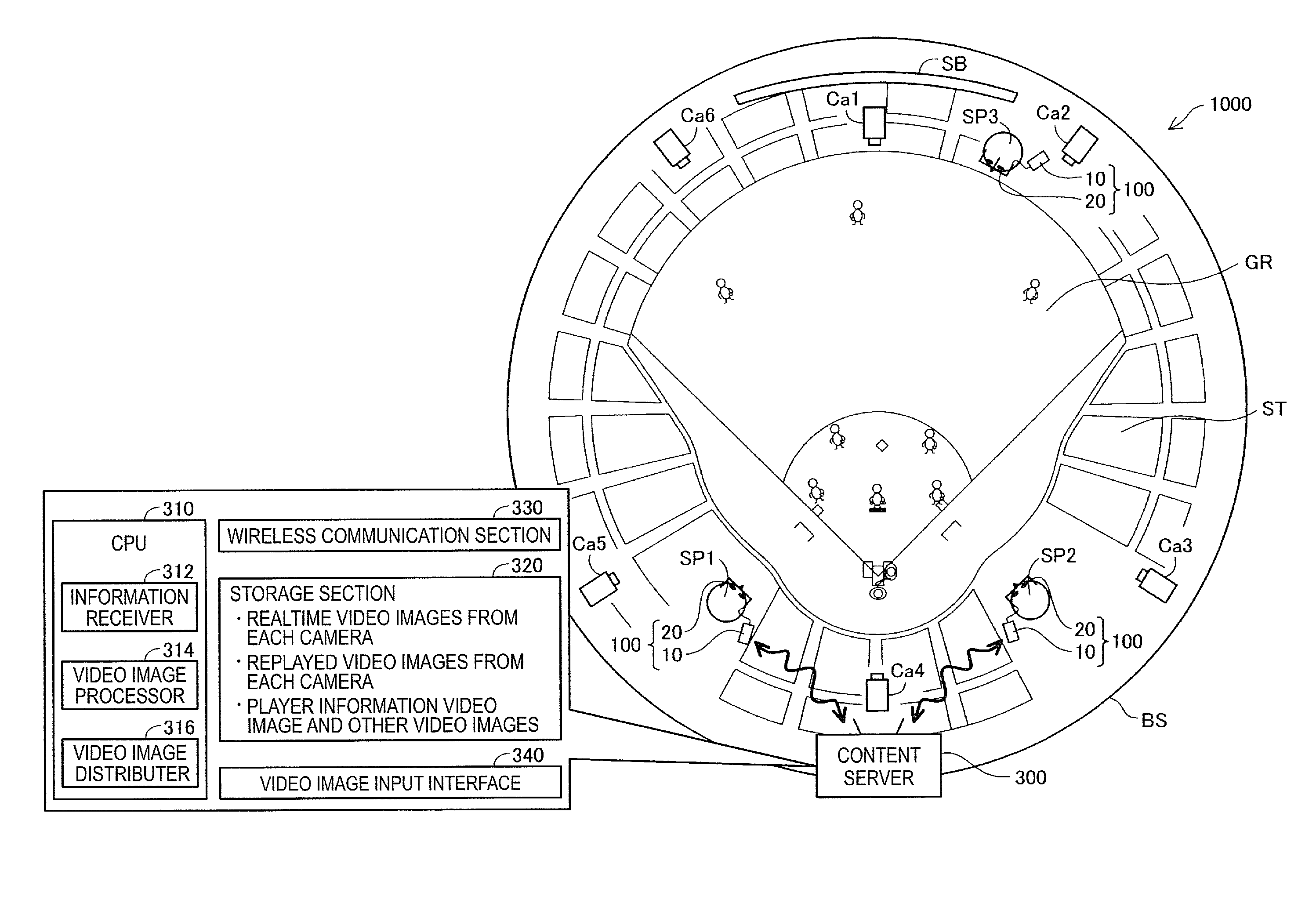
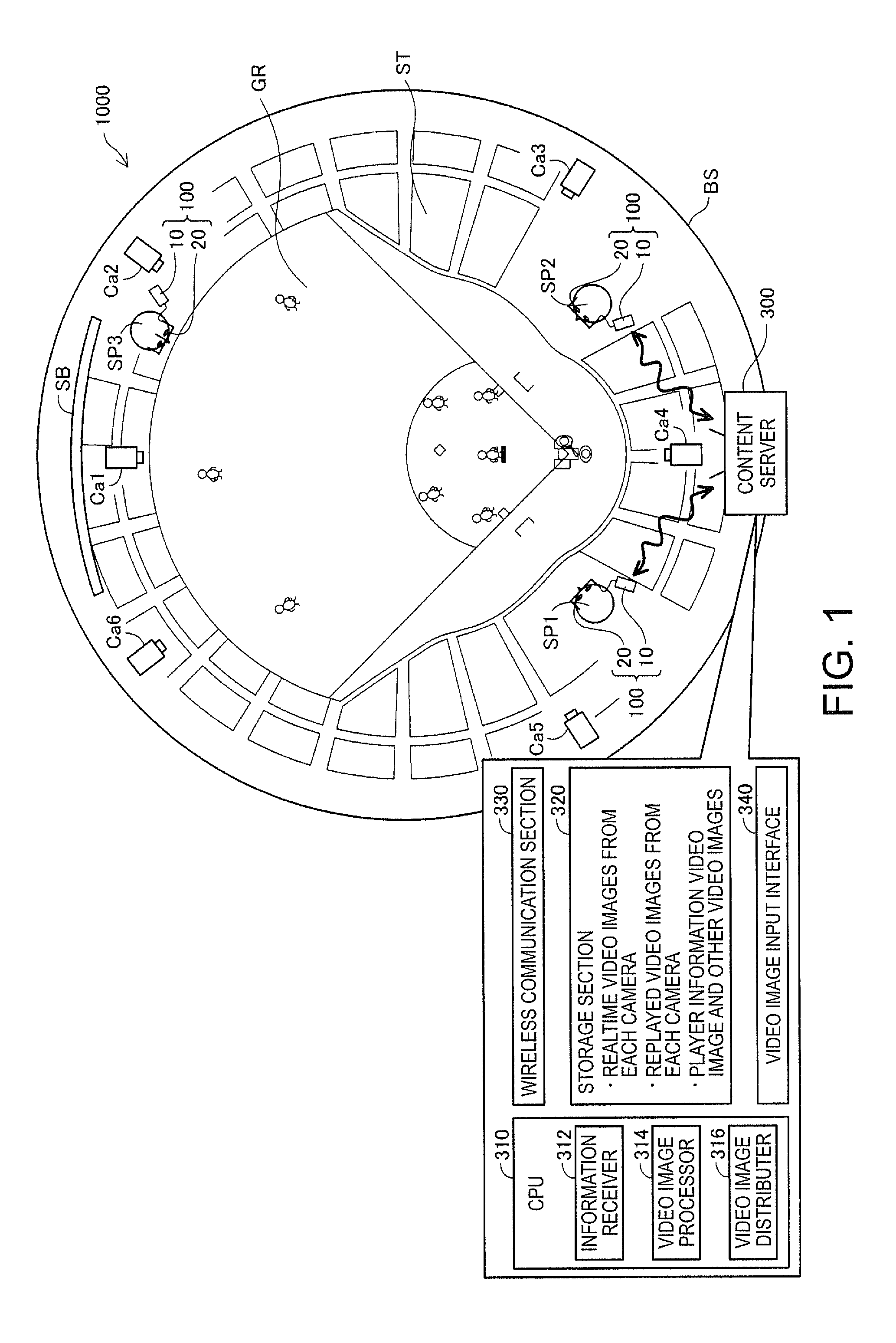
[0032]FIG. 1 is a descriptive diagram showing a schematic configuration of a video image display system 1000 in a first embodiment of the invention. The video image display system 1000 in the present embodiment is a system used in a baseball stadium BS. In the example shown in FIG. 1, spectators SP who each wear a head mounted display 100 (which will be described later in detail) are watching a baseball game in a watching area ST provided around a ground GR of the baseball stadium BS.

[0033]The video image display system 1000 includes a content server 300. The content server 300 includes a CPU 310, a storage section 320, a wireless communication section 330, and a video image input interface 340. The storage section 320 is formed, for example, of a ROM, a RAM, a DRAM, and a hard disk drive. The CPU 310, which reads and executes a computer program stored in the storage section 320, functions as an information receiver 312, a video image processer 314, and a video im...

second embodiment

B. Second Embodiment

[0077]FIG. 8 is a flowchart showing the procedure of an automatic video image selection process in a second embodiment. FIGS. 9A to 9C are descriptive diagrams showing a summary of the automatic video image selection process in the second embodiment. FIG. 9A shows that the spectator SP1 is sitting on an infield seat in the watching area ST and watching a baseball game, as in FIG. 7A.

[0078]When the automatic video image selection process starts, the game watch assistant 142 (FIG. 3) of the head mounted display 100 instructs the GPS module 134 to detect the current position (step S122), instructs the nine-axis sensor 66 to detect the orientation of the user's face (step S132), and transmits positional information representing the current position and motion information representing the orientation of the face to the content server 300 via the wireless communication section 132 (step S142).

[0079]The video image distributor 316 of the content server 300 having receiv...


PUM


Abstract

A video image display system including an information apparatus and a transmissive head mounted display that allows a user to visually recognize video images distributed from the information apparatus as virtual images is provided. The information apparatus includes a video image distributor that distributes video images corresponding to a specific geographic region to the head mounted display. The head mounted display includes a motion detector that detects motion of the user's head and allows the user to visually recognize, as virtual images, video images selected based on motion information representing the motion.

Description

BACKGROUND[0001]1. Technical Field[0002]The present invention relates to a video image display system and a head mounted display.[0003]2. Related Art[0004]There is a known head mounted display (HMD) that is a display mounted on the head. A head mounted display generates image light representing an image, for example, by using a liquid crystal display and a light source and guides the generated image light to user's eyes by using a projection system and a light guide plate to allow the user to visually recognize a virtual image. Such a head mounted display is classified into two types, a transmissive type in which the user can visually recognize an outside scene as well as a virtual image (optically transmissive type and video transmissive type) and a non-transmissive type in which the user cannot visually recognize an outside scene.[0005]There is a known video image display system of related art that has cameras installed, for example, at a variety of places and on vehicles in a rac...

Claims


Application Information

Patent Timeline
IPC IPC(8): G06F3/01
CPCG06F3/012G01S19/14G02B27/017G02B2027/0138G02B2027/014G02B2027/0187
Inventor KOBAYASHI, SHINICHI
Owner SEIKO EPSON CORP
Why Eureka
Try Eureka