

Disk drive suspension
a technology of drive suspension and drive shaft, which is applied in the direction of integrated arm assemblies, instruments, record information storage, etc., can solve the problems of amplified vibration adversely affecting the properties and achieve the effect of suppressing the vibration of the gimbal portion
- Summary
- Abstract
- Description
- Claims
- Application Information
AI Technical Summary
Benefits of technology
Problems solved by technology
Method used
Image

Examples
first embodiment
[0044]A disk drive suspension will now be described with reference to FIGS. 1 to 12.
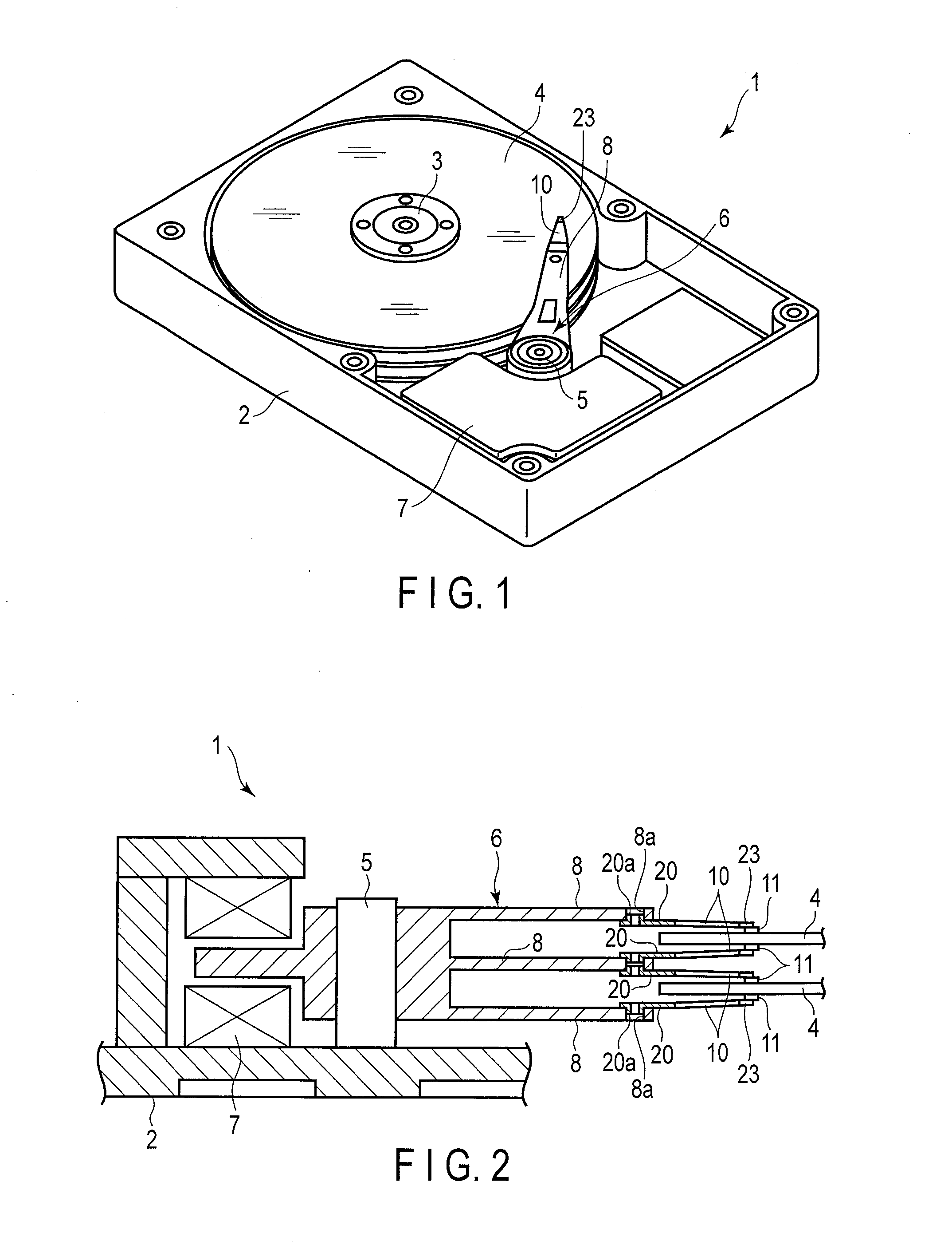
[0045]A disk drive (HDD) 1 shown in FIG. 1 comprises a case 2, disks 4 rotatable about a spindle 3, carriage 6 turnable about a pivot 5, positioning motor (voice coil motor) 7 for actuating the carriage 6, etc. The case 2 is sealed by a lid (not shown).
[0046]FIG. 2 is a sectional view schematically showing a part of the disk drive 1. As shown in FIGS. 1 and 2, the carriage 6 comprises arms (carriage arms) 8. A suspension 10 is mounted on the distal end portion of each arm 8. A slider 11, which constitutes a magnetic head, is provided on the distal end portion of the suspension 10. In a state where each disk 4 rotates at high speed, an air bearing is formed between the disk and the slider 11 as air flows in between the disk and slider.
[0047]If the carriage 6 is turned by the positioning motor 7, the suspension 10 moves radially relative to the disk 4. Thereupon, the slider 11 moves to a desired track...
fourth embodiment
[0086]FIG. 15 shows a microactuator mounting section 23C according to a A damper member 115 of this embodiment is disposed spanning between tongue portions 91 and 92 and supporting portions 70 and 71. The damper member 115 is formed with a circular opening 140 into which the dimple 100 (FIG. 10) is fitted, in a position corresponding to a hinge portion 93. Since other configurations and effects are common to the microactuator mounting sections 23, 23A 23B and23C, common numbers are used to designate common portions, and a description of those portions is omitted.
[0087]FIG. 16 shows frequency response characteristics based on PZT excitation of the microactuator mounting section comprising the damper member 115 shown in FIG. 15 and a microactuator mounting section without a damper member. In FIG. 16, full line S3 represents a frequency response characteristic curve of the microactuator mounting section comprising the damper member 115. Dash-dotted line S4 represents a frequency respo...
sixth embodiment
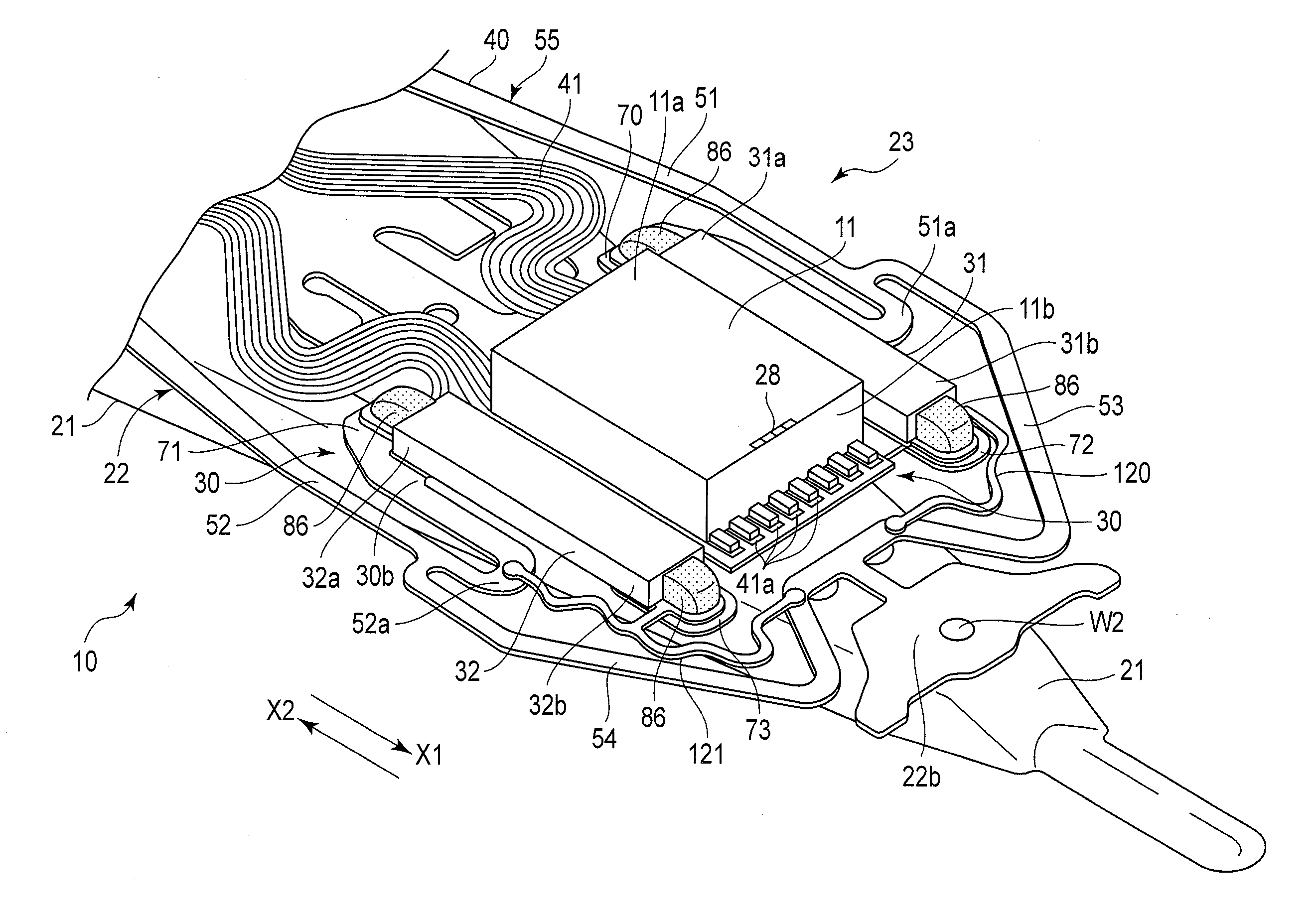
[0090]FIGS. 19 to 22 show a part of a microactuator mounting section 23E that is, that part where a microactuator element 32, one of a pair of microactuator elements, is located. That part where the other microactuator element is located is constructed in the same manner.
[0091]As shown in FIG. 19, an opening 111 is formed between first and second supporting portions 71 and 73 of a tongue 90 of a gimbal portion 30. The opening 111 is sufficiently large to accommodate the microactuator element 32 (FIG. 21). As shown in FIG. 20, a damper member 115 is secured to a first surface 30a of the gimbal portion 30 from below the opening 111 with a viscoelastic material layer 116 facing the opening 111.
[0092]As shown in FIG. 21, the microactuator element 32 is fitted into the opening 111 and placed on the viscoelastic material layer 116. This microactuator element 32 is secured to the damper member 115 by the adhesive force of the viscoelastic material layer 116. Further, opposite end portions...
PUM
 Abstract
Description
Claims
Application Information