Optical communication module

a communication module and optical technology, applied in the field of optical communication modules, can solve the problems of deformation of the guide pin or the optical member, the optical communication properties have worsened, etc., and achieve the effect of suppressing the locational misalignmen

Inactive Publication Date: 2014-03-27
HITACHI METALS LTD
View PDF3 Cites 12 Cited by
  • Summary
  • Abstract
  • Description
  • Claims
  • Application Information

AI Technical Summary

Benefits of technology

[0015]In view of the foregoing circumstances, it is an object of the present invention to provide an optical communication module, which allows a mechanical and simple alignment between an optical member and an optical element array, and which is capable of suppressing a locational misalignment, even in the event of thermal expansion or contraction of the optical member.
[0034]According to the invention, it is possible to provide the optical communication module, which allows a mechanical and simple alignment between the optical member and the optical element array, and which is capable of suppressing a locational misalignment, even in the event of thermal expansion or contraction of the optical member.

Problems solved by technology

Consequently, a locational misalignment has occurred between the optical element array and the optical member which are required to be aligned with high precision, and optical communication properties have worsened.
The method disclosed by JP-A-2006-65358 has been questionable in that it has failed to suppress the occurrence of the locational misalignment between the optical element array and the optical member due to such temperature variations, and further the thermal expansion of the optical member relative to the optical element array or the supporting member has been likely to cause deformation of the guide pins or the optical member.

Method used


Image

  • Optical communication module
  • Optical communication module
  • Optical communication module

Examples


Embodiment Construction

[0045]Below is described a preferred embodiment according to the invention, in conjunction with the accompanying drawings.

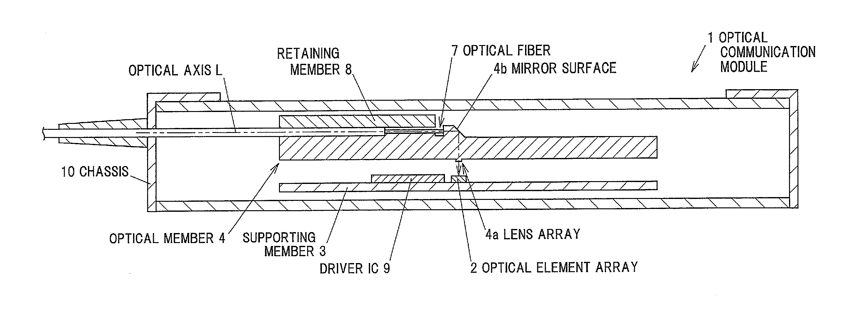
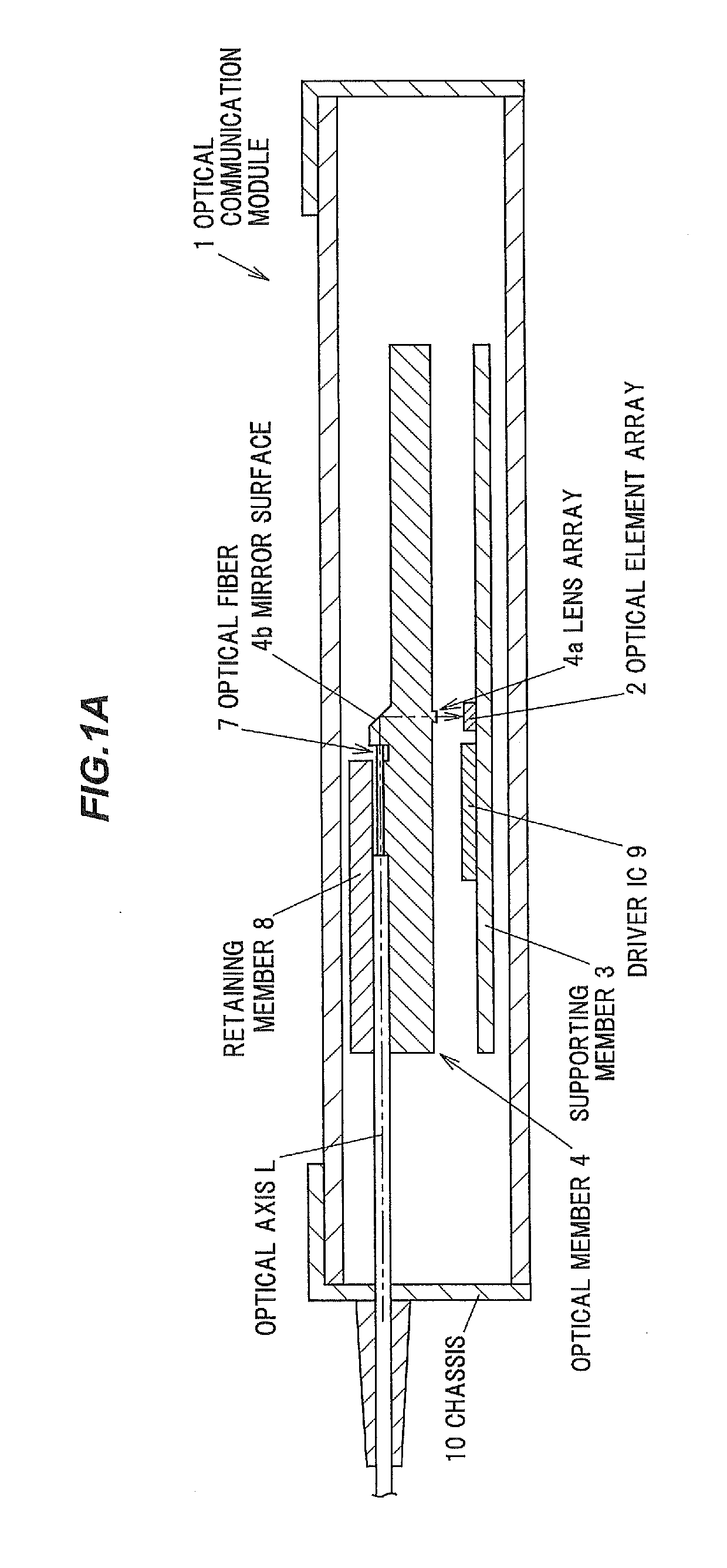
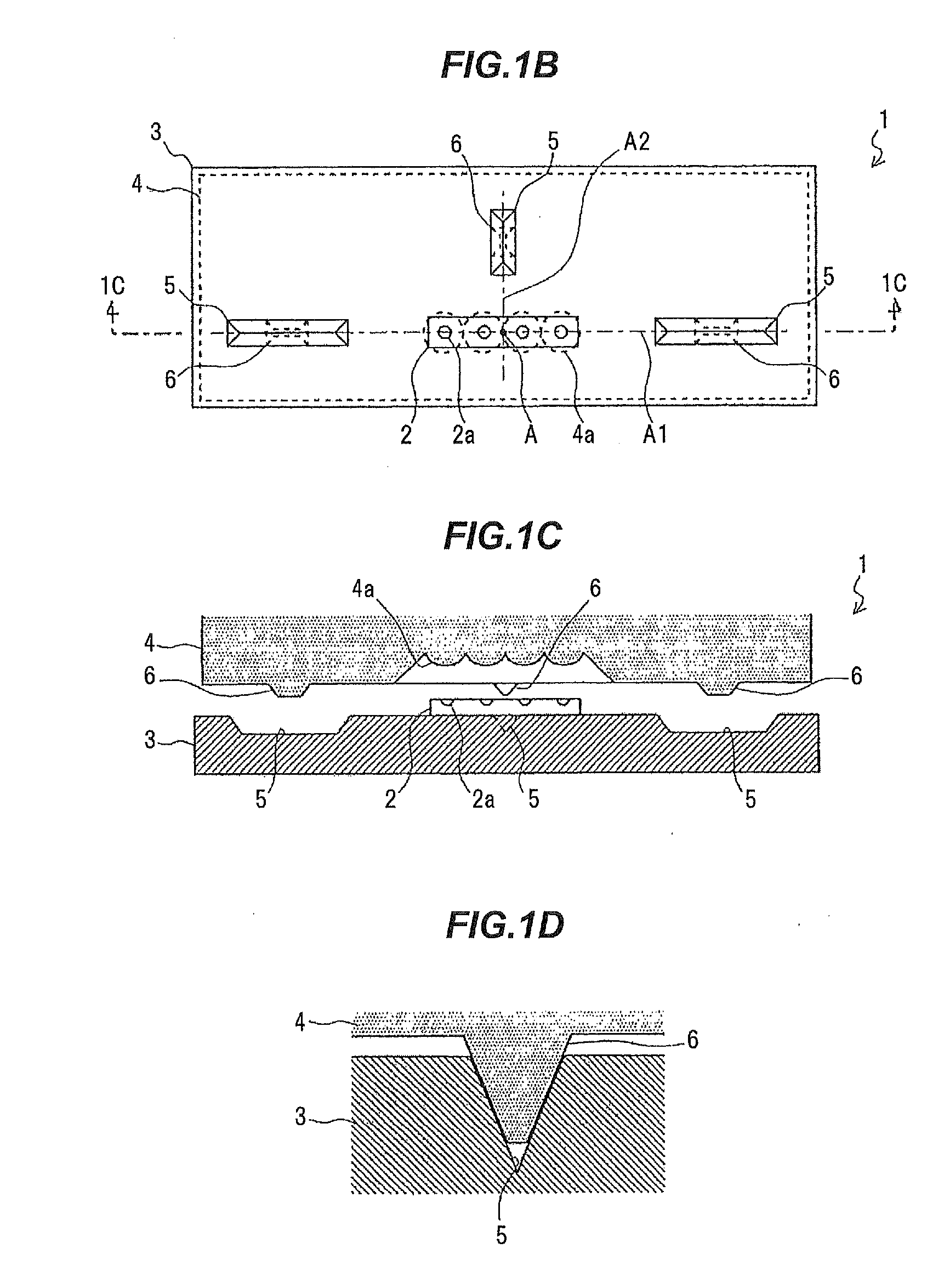
[0046]FIG. 1A is a longitudinal cross-sectional view showing an optical communication module in one embodiment according to the invention. FIG. 1B is an enlarged top view showing a part of the optical communication module in the embodiment according to the invention, through which an optical member is seen. FIG. 1C is a cross-sectional view along line 1C-1C of FIG. 1B. FIG. 1D is a cross-sectional view showing a mated state of a groove and a protrusion;

[0047]As shown in FIGS. 1A to 1C, the optical communication module 1 includes an optical element array 2, a supporting member 3, an optical member 4, optical fibers 7, a retaining member 8, a driver IC 9, and a chassis 10.

[0048]The optical element array 2 comprises light emitting elements arranged in an array, such as VCSELs or the like, or light receiving elements arranged in an array, such as photodiodes or the l...


PUM


Abstract

An optical communication module includes: an optical element array; a supporting member on which the optical element array is placed; an optical member for optically coupling the optical element array and a plurality of optical fibers together; a plurality of grooves provided in the supporting member or the optical member; and a plurality of protrusions provided on the optical member or the supporting member in correspondence with the grooves respectively. The grooves and the protrusions are mated together. The grooves are provided as being widened toward their openings. The grooves and the protrusions are each provided so that a location in a width direction at which no relative locational misalignment occurs therebetween lies on a line through the center of the optical element array. The grooves and the protrusions are each provided on at least two or more different lines through the center of the optical element array.

Description

[0001]The present application is based on Japanese patent application No.2012-212138 filed on Sep. 26, 2012, the entire contents of which are incorporated herein by reference.BACKGROUND OF THE INVENTION[0002]1. FIELD OF THE INVENTION[0003]This invention relates to an optical communication module, which converts an electrical signal into an optical signal and outputs it, or converts an optical signal into an electrical signal and outputs it.[0004]2. DESCRIPTION OF THE RELATED ART[0005]In optical communications, multichannel transmission is being used with increasing communication speed. An optical communication module for the multichannel transmission uses an optical element array which comprises easy-to-array surface emitting elements such as VCSELs (Vertical Cavity Surface Emitting LASERs) or the like or surface receiving elements such as photodiodes or the like, arranged in array. The optical element array is placed on a supporting member (a substrate) comprising a crystalline mat...

Claims


Application Information

Patent Timeline
Patent Type & Authority Applications(United States)
IPC IPC(8): G02B6/32
CPCG02B6/32G02B6/4214G02B6/423G02B6/4249
Inventor YONEZAWA, HIDENORISUNAGA, YOSHINORIISHIGAMI, YOSHIAKIYAMAZAKI, KINYA
Owner HITACHI METALS LTD
Why Eureka
Try Eureka