

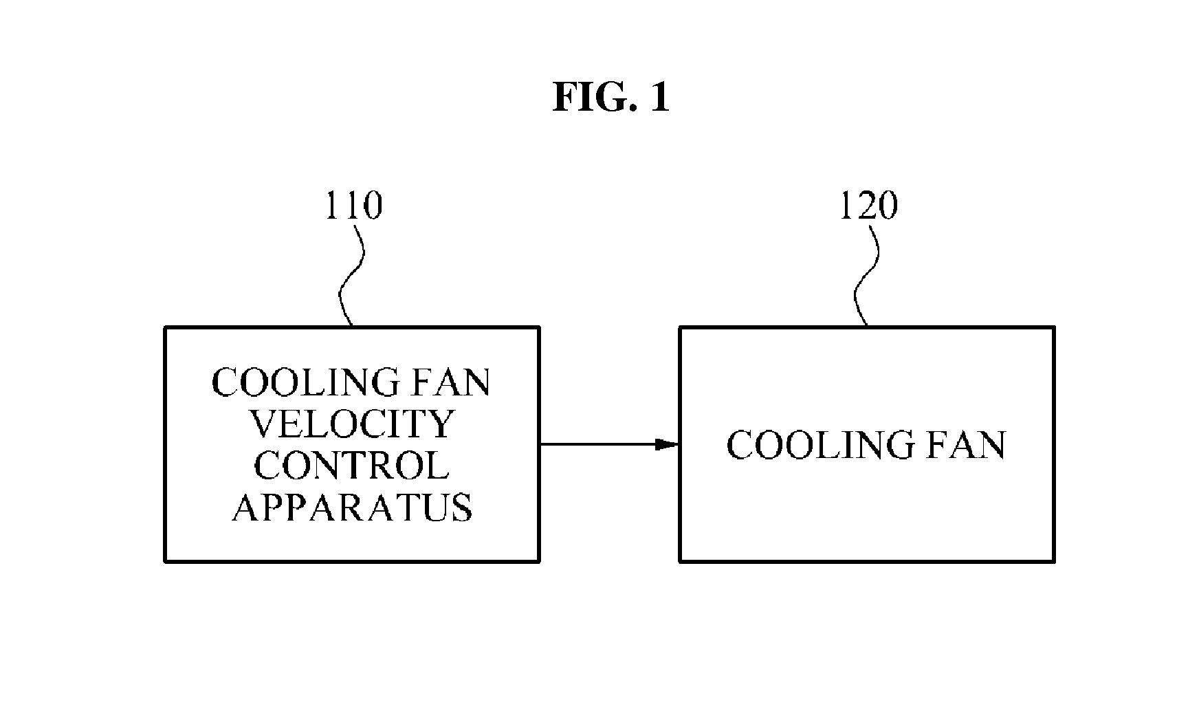
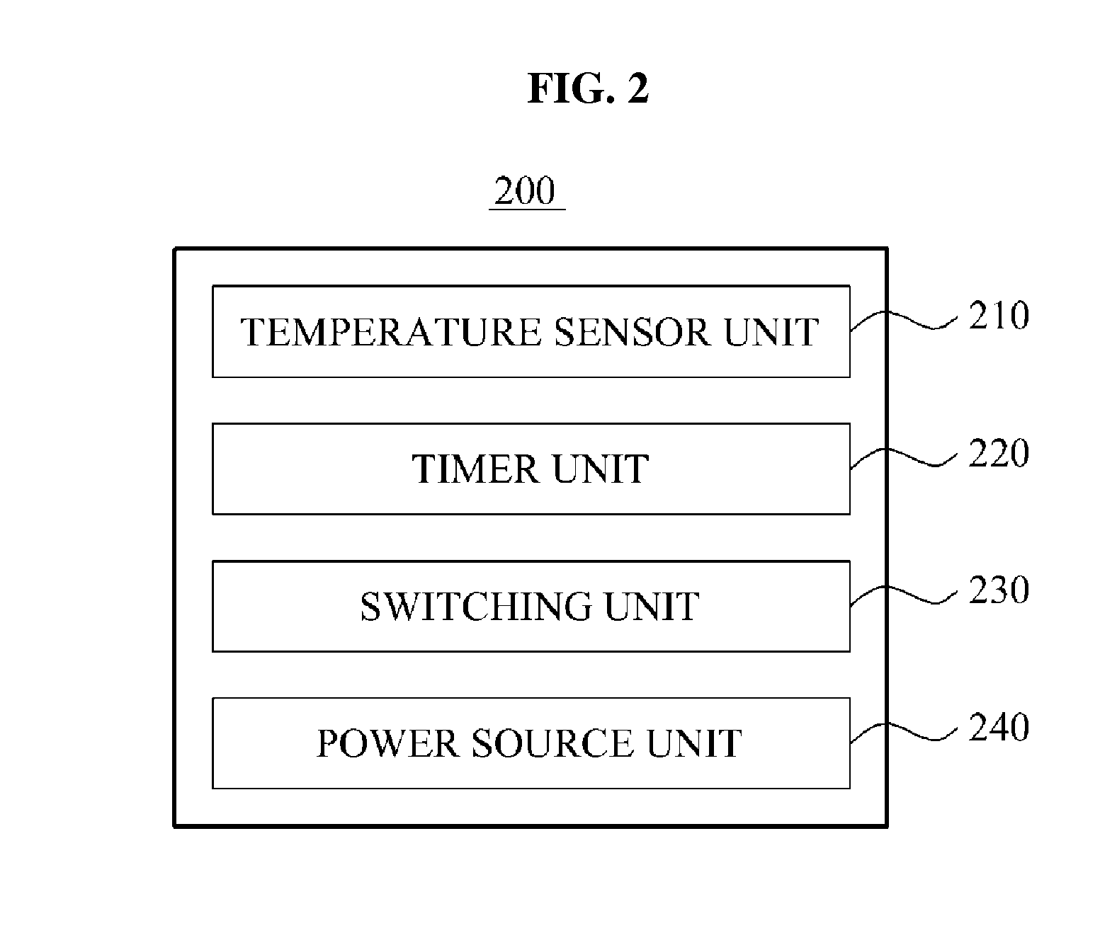
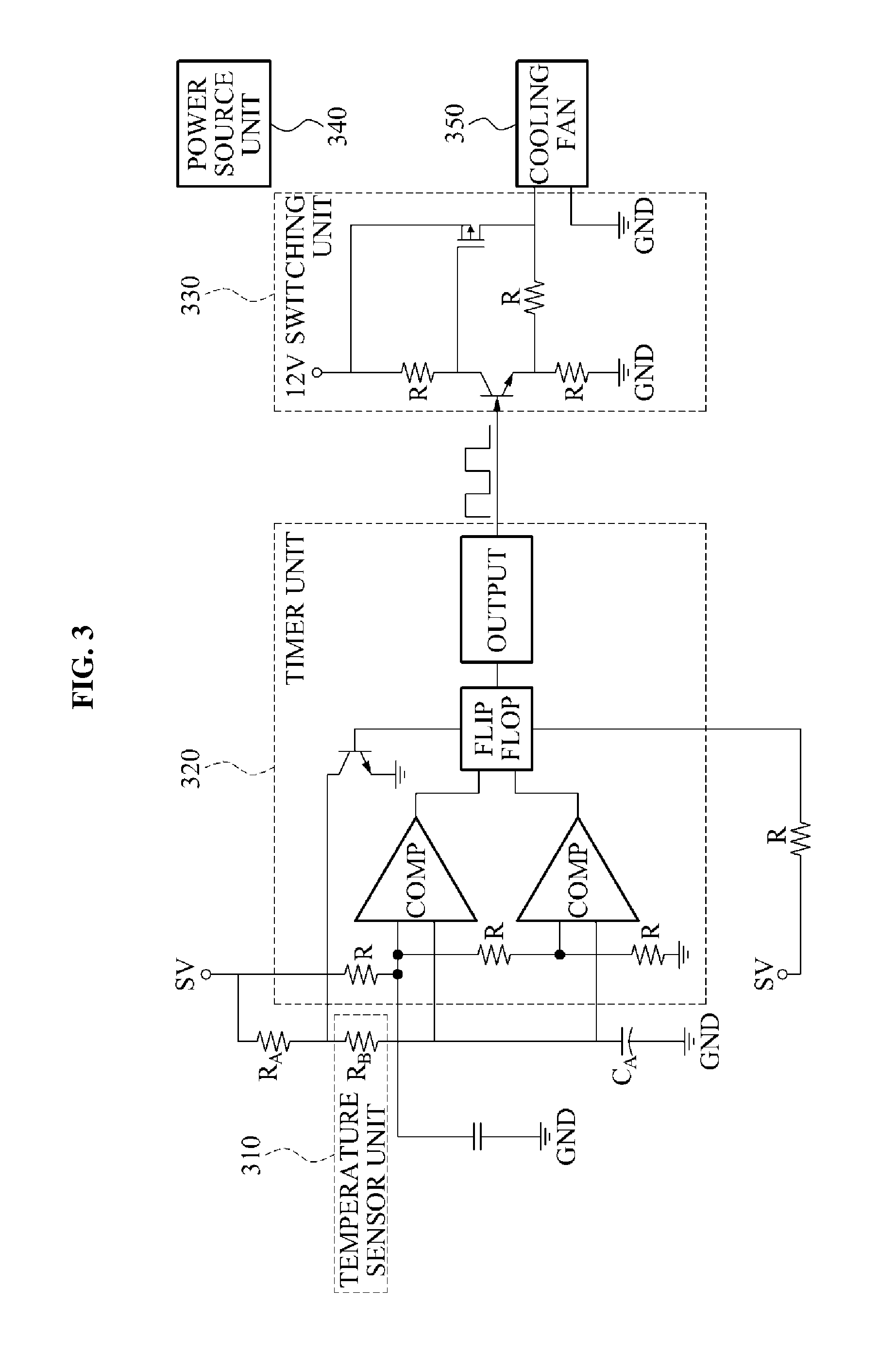
Cooling Fan Velocity Control Apparatus Using Timer and Temperature Sensor
a technology of timer and temperature sensor, which is applied in the direction of pump control, non-positive displacement fluid engine, climate sustainability, etc., can solve the problem of not providing the method of actively controlling the velocity of the cooling fan based on an increase in the temperature, and the above method has a limitation on the control of the cooling fan in response, so as to improve the function of reducing noise of the cooling fan, reduce costs, and reduce heat generation
- Summary
- Abstract
- Description
- Claims
- Application Information
AI Technical Summary
Benefits of technology
Problems solved by technology
Method used
Image

Examples
Embodiment Construction
[0024]Reference will now be made in detail to exemplary embodiments of the present invention, examples of which are illustrated in the accompanying drawings, wherein like reference numerals refer to the like elements throughout. Exemplary embodiments are described below to explain the present invention by referring to the figures.
[0025]Hereinafter, a cooling fan velocity control apparatus will be described in detail with reference to the accompanying drawings.
[0026]In a current set-top box (STB), an apparatus for actively controlling a velocity of a cooling fan based on an increase in an internal temperature is not provided. Typically, a microcontroller or a central processing unit (CPU) that has a function of a temperature sensor may perform pulse width modulation (PWM) on an internal signal, and may control a cooling fan. However, when a cooling fan needs to be used due to heating of a CPU that does not have the function of the temperature sensor, controlling of the velocity of th...
PUM
 Abstract
Description
Claims
Application Information