Cathode composite material, method for making the same, and lithium ion battery using the same

a lithium ion battery and composite material technology, applied in the direction of nickel compounds, cell components, alkali titanates, etc., can solve the problems of poor cycling life, and capacity loss of lithium ion batteries during cycling

Active Publication Date: 2014-03-27
TSINGHUA UNIV +1
View PDF5 Cites 28 Cited by
  • Summary
  • Abstract
  • Description
  • Claims
  • Application Information

AI Technical Summary

Problems solved by technology

Lithium ion batteries can experience capacity loss during charging and discharging cycles and a poor cycling life due to the capacity loss.
One reason for the capacity loss during the cycling is an un-reversible change of an intrinsic structure of a cathode active material that occurs during cycling.
Another reason for the capacity loss during the cycling is a cathode active material loss caused by a reaction between the cathode active material and the organic solvent that occurs when the cathode active material is in a lithium ion deintercalation state and thus has a high oxidability.
However, the stability improving problem during the cycling of the lithium ion battery has not been properly solved.

Method used


Image

  • Cathode composite material, method for making the same, and lithium ion battery using the same
  • Cathode composite material, method for making the same, and lithium ion battery using the same
  • Cathode composite material, method for making the same, and lithium ion battery using the same

Examples


example 1

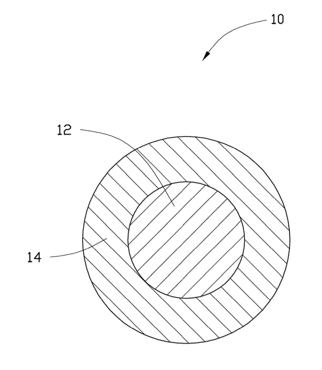
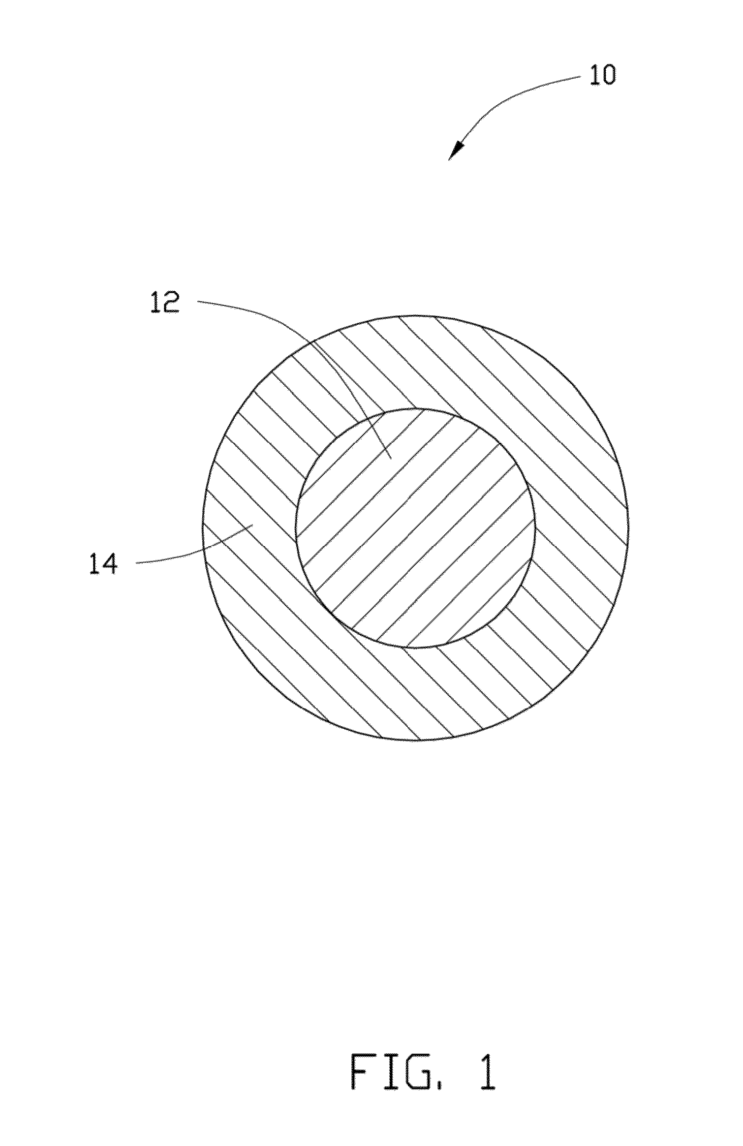
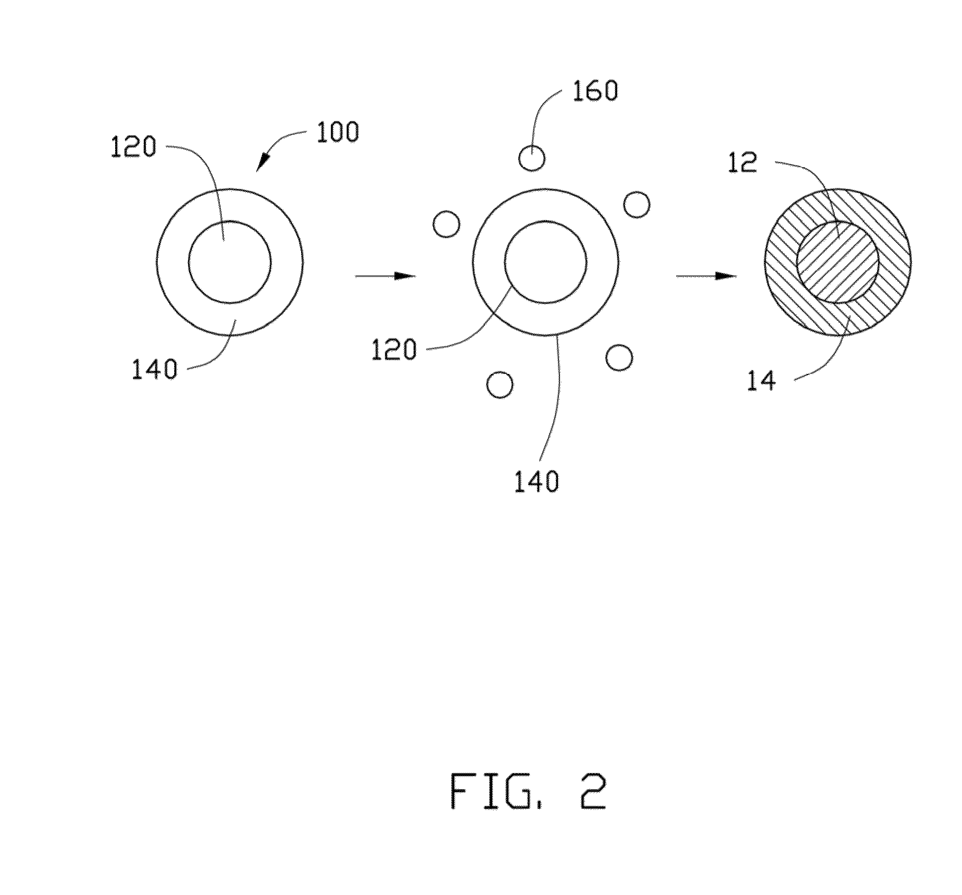
[0079]In Example 1, 0.25 g Co(OH)2 is ultrasonically dispersed in 10 mL of ethanol to achieve the solid-liquid mixture. Then, the tetrabutyl titanate is added into the solid-liquid mixture. A molar ratio between the tetrabutyl titanate and the Co(OH)2 is about 1:10. After adding the tetrabutyl titanate, the solid-liquid mixture is continuously ultrasonically vibrated to uniformly mix the tetrabutyl titanate and the Co(OH)2 in the ethanol. After that, the solid-liquid mixture is transferred into a dry and clean hydrothermal autoclave and reacted at about 150° C. for about 3 hours. After the hydrothermal synthesis, the amorphous TiO2 layer can be formed on the surface of the Co(OH)2, to form the composite precursor. The composite precursor and the LiOH.H2O are mixed in the stoichiometric ratio and are dried to remove the residual ethanol. Then the mixture of the composite precursor and the LiOH.H2O are heated to about 800° C. at a temperature increasing rate of about 3° C. / min, and is...

example 2

[0085]In Example 2, the cathode composite material is prepared using the same method as in Example 1, except that the Co(OH)2 is replaced by CoC2O4.xH2O.

example 3

[0086]In Example 3, 0.25 g MnOOH is ultrasonically dispersed in 10 mL of ethanol to achieve the solid-liquid mixture. Then, the tetrabutyl titanate is added into the solid-liquid mixture. A molar percentage of the tetrabutyl titanate to the MnOOH is about 5%. After adding the tetrabutyl titanate, the solid-liquid mixture is continuously ultrasonically vibrated to uniformly mix the tetrabutyl titanate and the MnOOH in the ethanol. After that, the solid-liquid mixture is transferred into a dry and clean hydrothermal autoclave and reacted at about 150° C. for about 3 hours. After the hydrothermal synthesis, the amorphous TiO2 layer can be formed on the surface of the MnOOH, to form the composite precursor. The composite precursor and the LiOH.H2O are mixed in the stoichiometric ratio and are dried to remove the residual ethanol. Then the mixture of the composite precursor and the LiOH.H2O are heated to about 800° C. at a temperature increasing rate of about 3° C. / min, and is heated at ...


PUM

PropertyMeasurementUnit
thicknessaaaaaaaaaa
sizeaaaaaaaaaa
thicknessaaaaaaaaaa

Abstract

A cathode composite material includes a cathode active material and a coating layer coated on a surface of the cathode active material. A material of the coating layer is a lithium metal oxide having a crystal structure belonging to C2/c space group of the monoclinic crystal system. The present disclosure also relates to a lithium ion battery including the cathode composite material.

Description

CROSS-REFERENCE TO RELATED APPLICATIONS[0001]This application claims all benefits accruing under 35 U.S.C. §119 from China Patent Application No. 201210369003.3, filed on Sep. 27, 2012 in the China Intellectual Property Office, the content of which is hereby incorporated by reference. This application is related to commonly-assigned applications entitled, “CATHODE COMPOSITE MATERIAL, METHOD FOR MAKING THE SAME, AND LITHIUM ION BATTERY USING THE SAME”, filed **** (Atty. Docket No. US47009); “CATHODE COMPOSITE MATERIAL AND LITHIUM ION BATTERY USING THE SAME”, filed **** (Atty. Docket No. US47013), “CATHODE COMPOSITE MATERIAL AND LITHIUM ION BATTERY USING THE SAME”, filed **** (Atty. Docket No. US47015), “CATHODE COMPOSITE MATERIAL AND LITHIUM ION BATTERY USING THE SAME”, filed **** (Atty. Docket No. US47016), “CATHODE COMPOSITE MATERIAL AND LITHIUM ION BATTERY USING THE SAME”, filed **** (Atty. Docket No. US47017), “CATHODE COMPOSITE MATERIAL AND LITHIUM ION BATTERY USING THE SAME”, f...

Claims


Application Information

Patent Timeline
Patent Type & Authority Applications(United States)
IPC IPC(8): H01M4/485
CPCH01M4/485H01M4/505H01M4/624H01M10/0525C01G23/005C01G25/00C01G45/1242C01G51/42C01G53/50C01P2002/52C01P2002/72C01P2002/76C01P2004/80C01P2004/84C01P2006/40H01M4/366H01M4/525H01M10/052Y02E60/10H01M4/131H01M4/1391
Inventor LI, YA-DONGLU, JUNNAN, CAI-YUNLI, LI-HONGPENG, QING
Owner TSINGHUA UNIV
Why Eureka
Try Eureka