Method and apparatus for treating pelvic pain

a pelvic pain and pelvis technology, applied in the field of pelvic pain treatment methods and apparatuses, can solve the problems of long-standing pelvic pain problems, inability to afford the ongoing level of treatment, and inability to access pelvic pain professionals competent in internal trigger point releas

Active Publication Date: 2014-03-27
NEW PELVIC PAIN TECH INC
View PDF7 Cites 14 Cited by
  • Summary
  • Abstract
  • Description
  • Claims
  • Application Information

AI Technical Summary

Problems solved by technology

Pelvic pain has long been a problem among women and men.
Many pelvic pain patients do not have access to professionals competent in internal trigger point release, are not able to afford the ongoing level of treatment, or are not able to find the time necessary to receive trigger point release.
Thus, many patients have an urgent need for ongoing trigger point release related to pelvic pain that remains unmet due to the financial and time related problems existing in conventional professional treatment of internal trigger points and to the scarcity of internal trigger point practitioners.
Previously known self-treatment apparatuses have proven ineffective for internal trigger point release because they were designed for other purposes and not for internal trigger point release.
Previous apparatuses have not had the structural design to enable the patient to locate the often hard to find internal trigger points, nor have they provided any assistance in applying the appropriate pressure to release the trigger point and, importantly, at the same time to cause no bleeding tissue damage or perforation.

Method used


Image

  • Method and apparatus for treating pelvic pain
  • Method and apparatus for treating pelvic pain
  • Method and apparatus for treating pelvic pain

Examples


first embodiment

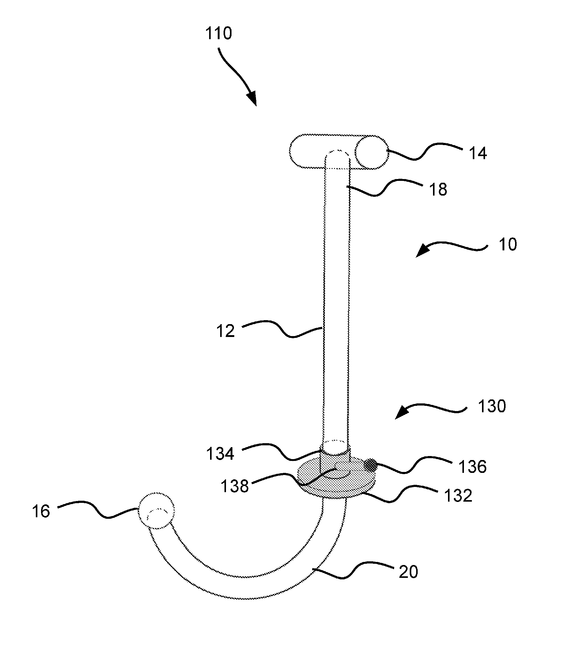
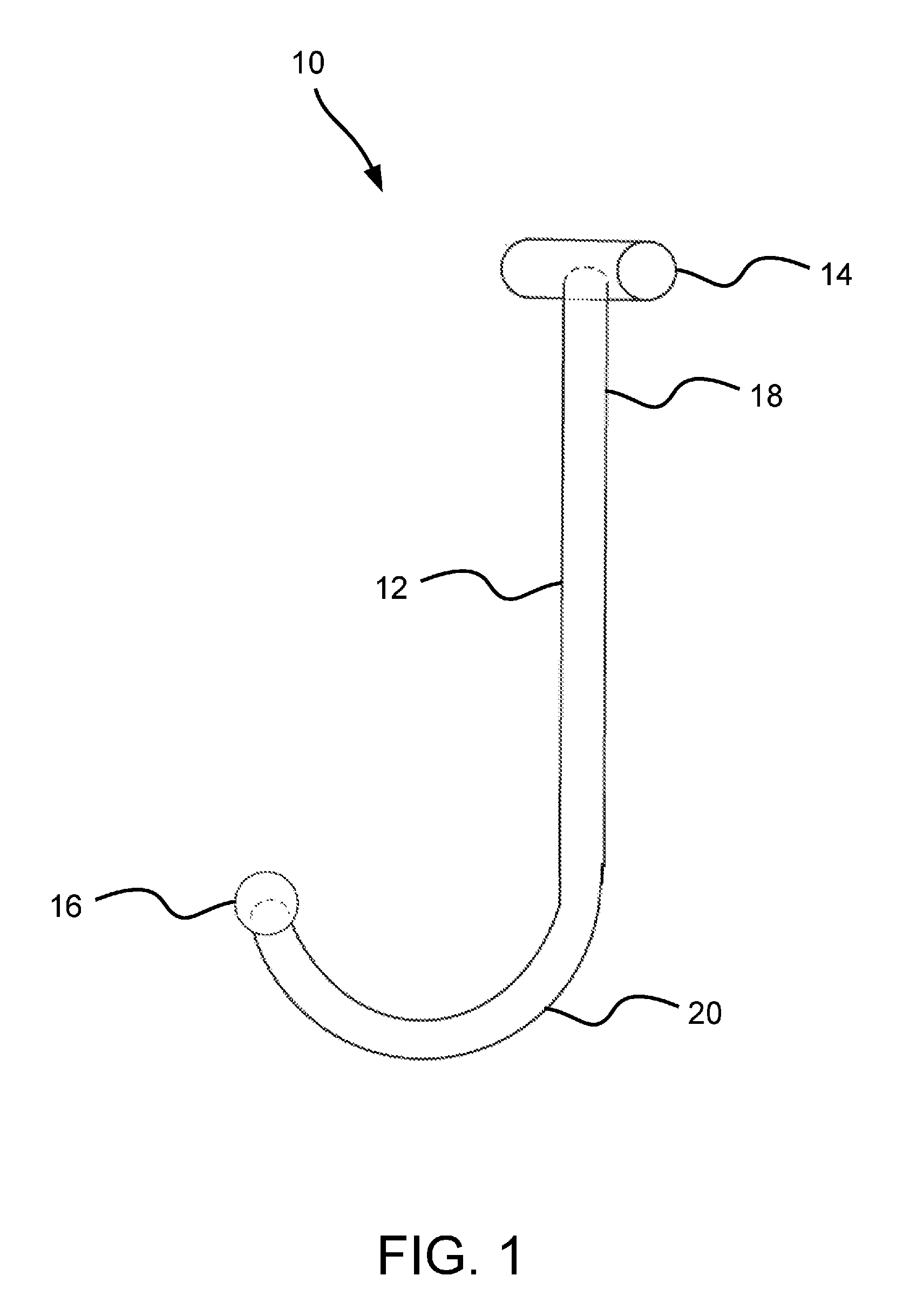
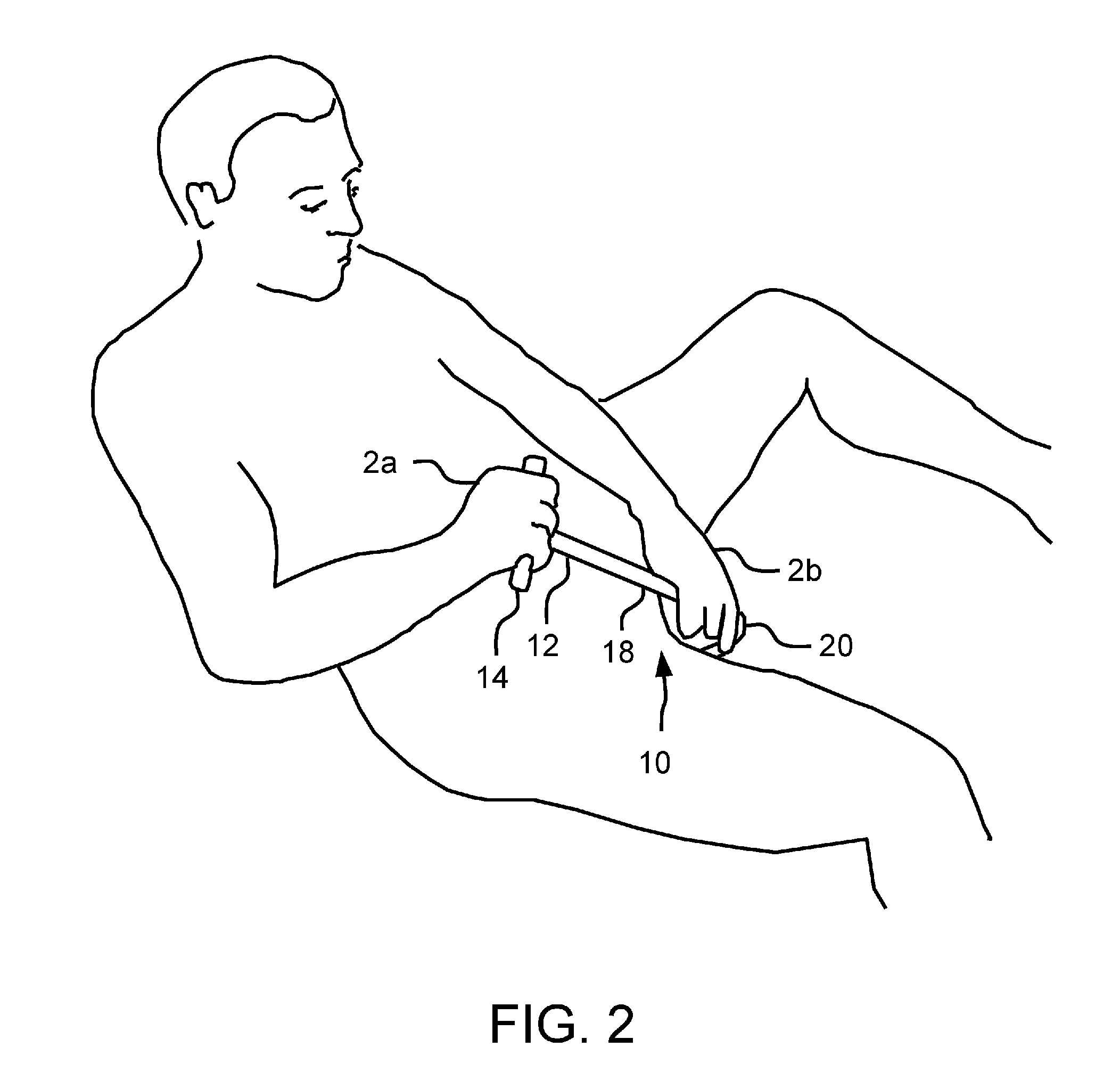
[0027]Referring to FIGS. 1-3, there is shown an apparatus 10 in accordance with the invention. The apparatus 10 includes a substantially j-shaped rod or wand 12, a handle member 14 connected to a first end of the wand 12, and a pressure applicator 16 connected to a second end of the wand 12. The handle member 14 and the pressure applicator 16 are connected to the wand 12 in any suitable conventional manner. The wand 12, the handle member 14, and the pressure applicator 16 may be fabricated from any suitable material, such as acrylic.

[0028]The wand 12 is a continuous member that has a straight portion 18 that extends from the handle member 14 for approximately ten inches before reaching a semicircular portion 20. The semicircular portion 20 defines an arc of approximately 180 degrees. However, it should be understood that the semicircular portion 20 need not be exactly semicircular, as long as it forms a generally u-shaped curve. The wand 12 may be either hollow or solid, as desired....

tenth embodiment

[0054]FIG. 12 is a side view of an apparatus 910 for treating pelvic pain according to the invention. The apparatus 910 includes a wand 912, which is as described in previous embodiments and can include or be used with the various features shown in previous embodiments. A pressure applicator 920 is located at one end of the wand 912. In the illustrated example, a narrowed end 914 of the wand is received within a bore 922 defined by the pressure applicator, and a nominal outer diameter of the wand 912 is wider than the narrowed end and is substantially the same as an outside diameter of a base 924 of the pressure applicator 920. At least part of the end portion 926 of the pressure applicator has a substantially spherical shape, which changes to a frustroconical shape at a transition section 928 that provides a gradual change in diameter for the pressure applicator 920, which can aid insertion and removal of the pressure applicator, thus improving patient comfort.

[0055]In one implemen...


PUM


Abstract

A hand-held internal therapeutic massager includes a rod having a first portion that defines a curve and a second portion that is substantially straight. The first portion of the rod is adapted to be inserted into a patient's body. A curvature of the curve defined by the first portion of the rod is sufficient to prevent the second portion of the rod from entering a patient's body. A handle is located on the second portion of the rod and a pressure applicator on the first portion of the rod is adapted to be inserted into the patient's body for engagement with a localized area of myofascial tissue. A vibratory device is disposed within the handle and is operable to generate vibrations. The vibrations generated by the vibratory device are conducted through the rod to the pressure applicator to the localized area of myofascial tissue.

Description

CROSS-REFERENCE TO RELATED APPLICATIONS[0001]This application is a continuation-in-part of U.S. patent application Ser. No. 13 / 723,263, filed Dec. 21, 2012, which is a continuation of U.S. patent application Ser. No. 12 / 115,807, filed May 6, 2008, which claims the benefit of U.S. Provisional Patent Application No. 60 / 928,033, filed May 7, 2007.FIELD OF THE INVENTION[0002]The present invention relates to a method and apparatus for treating pelvic pain in women and men.BACKGROUND OF THE INVENTION[0003]Pelvic pain has long been a problem among women and men. Conventional medicine has treated pelvic pain in various ways including, 1) an organ-specific focus in which pelvic pain is believed to be a symptom of inflammation in the bladder, inflammation or infection in the prostate gland, or pathology of the uterus; 2) focus on the idea of the pudendal nerve being entrapped and needing release; 3) focus on an autoimmune process; or 4) focus supposed on psychiatric problems deriving from a f...

Claims


Application Information

Patent Timeline
Patent Type & Authority Applications(United States)
IPC IPC(8): A61H23/00A61H19/00
CPCA61H19/40A61H23/00A61N1/0512A61N1/0524A61N1/36007A61N1/36021A61B5/036A61B5/742A61B2560/04A61B2562/0247A61H21/00A61H23/0245A61H23/0263A61H2015/0042A61H2201/0173A61H2201/5043A61H2201/5071
Inventor WISE, DAVID
Owner NEW PELVIC PAIN TECH INC
Why Eureka
Try Eureka