Tire air pressure monitor device

a technology for monitoring devices and tires, which is applied in vehicle tyre testing, instruments, transportation and packaging, etc., can solve the problems of deteriorating detection accuracy and difficulty in and achieve the effect of more accurately detecting the rotational position of transmitters

Active Publication Date: 2014-03-27
NISSAN MOTOR CO LTD
View PDF6 Cites 24 Cited by
  • Summary
  • Abstract
  • Description
  • Claims
  • Application Information

AI Technical Summary

Benefits of technology

[0005]In order to achieve the above object, according to the present invention, the rotational position at the time of transmission from the transmitter is estimated based on the rotational positions of the wheel which are input immediately before a receiving start of the wireless signal from the transmitter and immediately after the receipt completion ...

Problems solved by technology

However, if the rotational position information of the wheel detected by the vehicle body side is input sporadically at a predetermined time interval, it may ...

Method used


Image

  • Tire air pressure monitor device
  • Tire air pressure monitor device
  • Tire air pressure monitor device

Examples


first embodiment

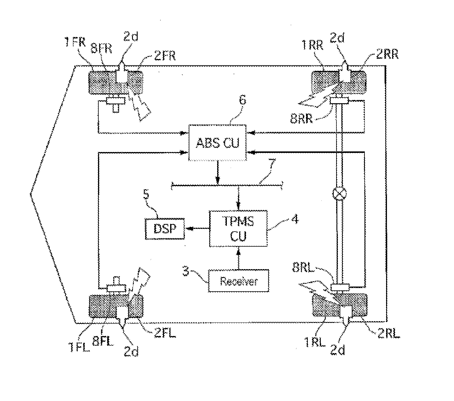
[0021]FIG. 1 is a configuration diagram illustrating a tire air or pneumatic pressure monitoring device in a In this figure, the end letters annexed to each reference sign is intended to indicate as follows: FL stands for the left front wheel, FR stands for the right front wheel, RL stands for the left rear wheel, and RR stands for the right rear wheel, respectively. In the following description, when not specifically necessary, the description of FL, FR, RL and RR will be omitted.

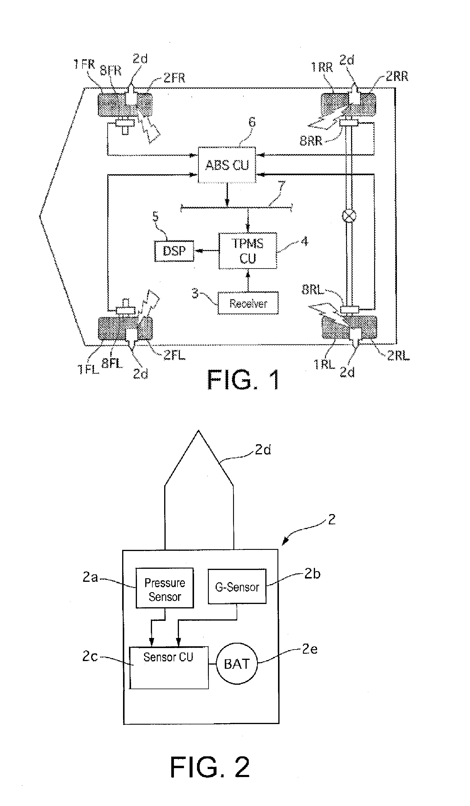
[0022]The tire pneumatic or air pressure monitoring device in the first embodiment is provided with TPMS (tire pressure monitoring system) sensors 2, a receiver 3, a TPMS control unit (TPMSCU) 4, a display 5, and wheel speed sensors 8. A TPMS sensor 2 is installed on each of the wheels 1, and the receiver 3, the TPMSCU 4, the display 5 and the wheel speed sensors 8 are arranged on the side of the vehicle body.

[0023]The TPMS sensor 2 is installed at the position of an air valve (not shown in the figure) of...

second embodiment

[0129]In the tire pressure monitoring device in the second embodiment, the following effects may be obtained.

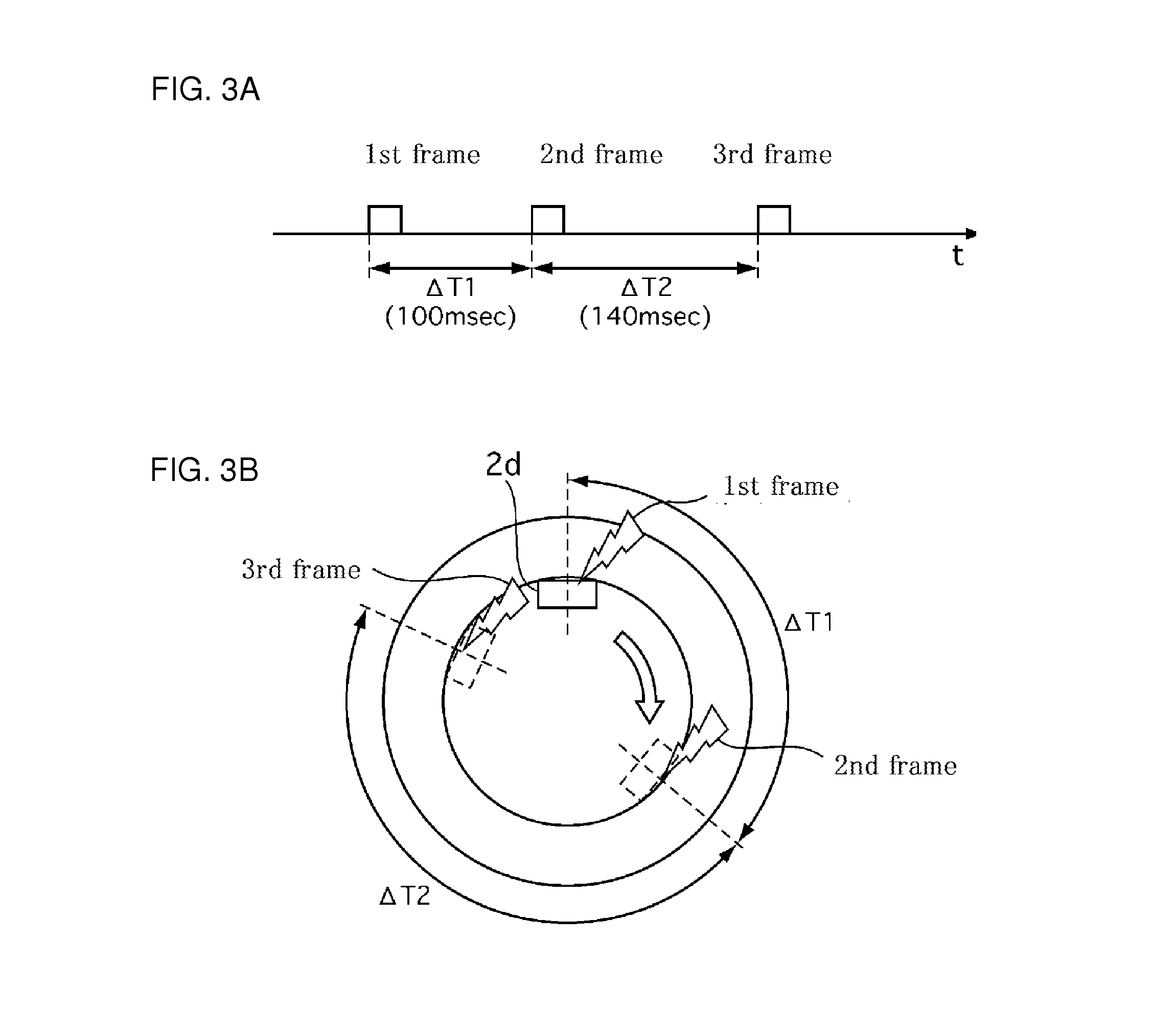
[0130]The transmitter 2d transmits each frame (first to fourth frames) with a predetermined rotational position interval (90 degrees for example). Thus, combined with the information of the predetermined rotational position interval (90 degrees), the transmission order information (frame number) added to each frame (second, third frames) represents the rotational position information of the transmitter 2d at the time of transmission of the frame (second, third frames). Therefore, the vehicle body-side rotational position estimate mechanism (rotational position calculation unit 4a), based on the received information (receipt completion time t4′, and frame number) of the received one (for example of the second frame) among the plurality of the frames, may estimate the predetermined rotational position (number of teeth zt2 at top point).

[0131]In the third embodiment, in a fixed ...

third embodiment

[0136]Note that the dispersion characteristic value X of the number of teeth at the reference position may be calculated for each group. In the third embodiment, by converting all the received data into the reference position of the first group (number of teeth at top point), a significant difference in dispersion value X of the self-wheel and the other wheels may be produced more rapidly. Therefore, it is possible to estimate the wheel position of the TPMS sensor 2 more accurately within short time. Note that the reference position for the wheel position determination (calculation of the dispersion characteristic value) may not be restricted to the reference position (top point) of the first group, but may be collected or aggregated to a reference position (rear most point) of the other group (second group, for example).

[0137]The TPMS sensor 2 (transmitter 2d), as in the second embodiment, may be configured to transmit the frames of each group (first to third frames) at predetermin...


PUM


Abstract

Provided is a tire air pressure monitoring device capable of accurately determining the wheel position of a transmitter. The tire air pressure monitoring device comprises: a transmitter installed on each wheel for transmitting detected air pressure information via a wireless signal; a rotational position detection mechanism disposed on the vehicle body side which detects the rotational position of each wheel and also outputs rotational position information to a communications line at prescribed time intervals; and a vehicle body side rotation position estimation mechanism that estimates the rotational position (i.e., number of teeth) at the time of transmission by the transmitters, on the basis of the reception information for the wireless signal from the transmitters and the rotation position information for the wheels input via the communications line.

Description

CROSS-REFERENCE TO RELATED APPLICATIONS[0001]This national stage application claims priority to Japanese Patent Application No. 2011-110001 filed on May 17, 2011, and claims priority to Japanese Patent Application No. 2011-115005 filed on May 23, 2011, both of which are incorporated herein in their entirety.TECHNICAL FIELD[0002]The present invention relates to a tire pressure monitoring device for monitoring an air pressure of each tire of a vehicle.BACKGROUND[0003]Conventionally, Japanese Patent Application JP 2007-245982 A teaches a tire air pressure monitoring device for determining on which wheel a transmitter of a tire pressure sensor installed on a tire of each wheel is positioned.[0004]During a vehicle running, the transmitter rotates together with the wheel and the difference may occur in the rotation speeds among the respective wheels. Therefore, in order to accurately determine the wheel position of the transmitter, it is preferable to accurately detect a rotational positi...

Claims


Application Information

Patent Timeline
IPC IPC(8): G01M17/02
CPCG01M17/02B60C23/0416B60C23/0488B60C23/0489B60C23/0459
Inventor SHIMA, TAKASHISAKAGUCHI, KAZUOTERADA, SYOJI
Owner NISSAN MOTOR CO LTD
Why Eureka
Try Eureka