
Grill shutter

Inactive Publication Date: 2014-04-03
YACHIYO IND CO LTD
View PDF14 Cites 13 Cited by
  • Summary
  • Abstract
  • Description
  • Claims
  • Application Information

AI Technical Summary

Benefits of technology

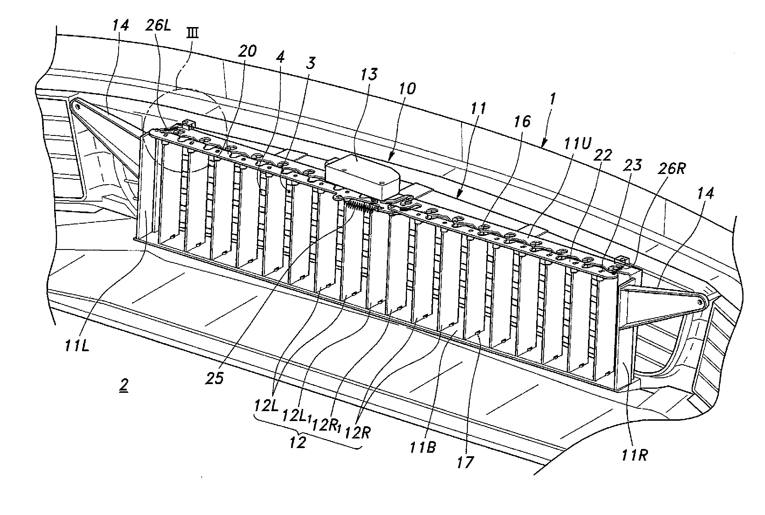
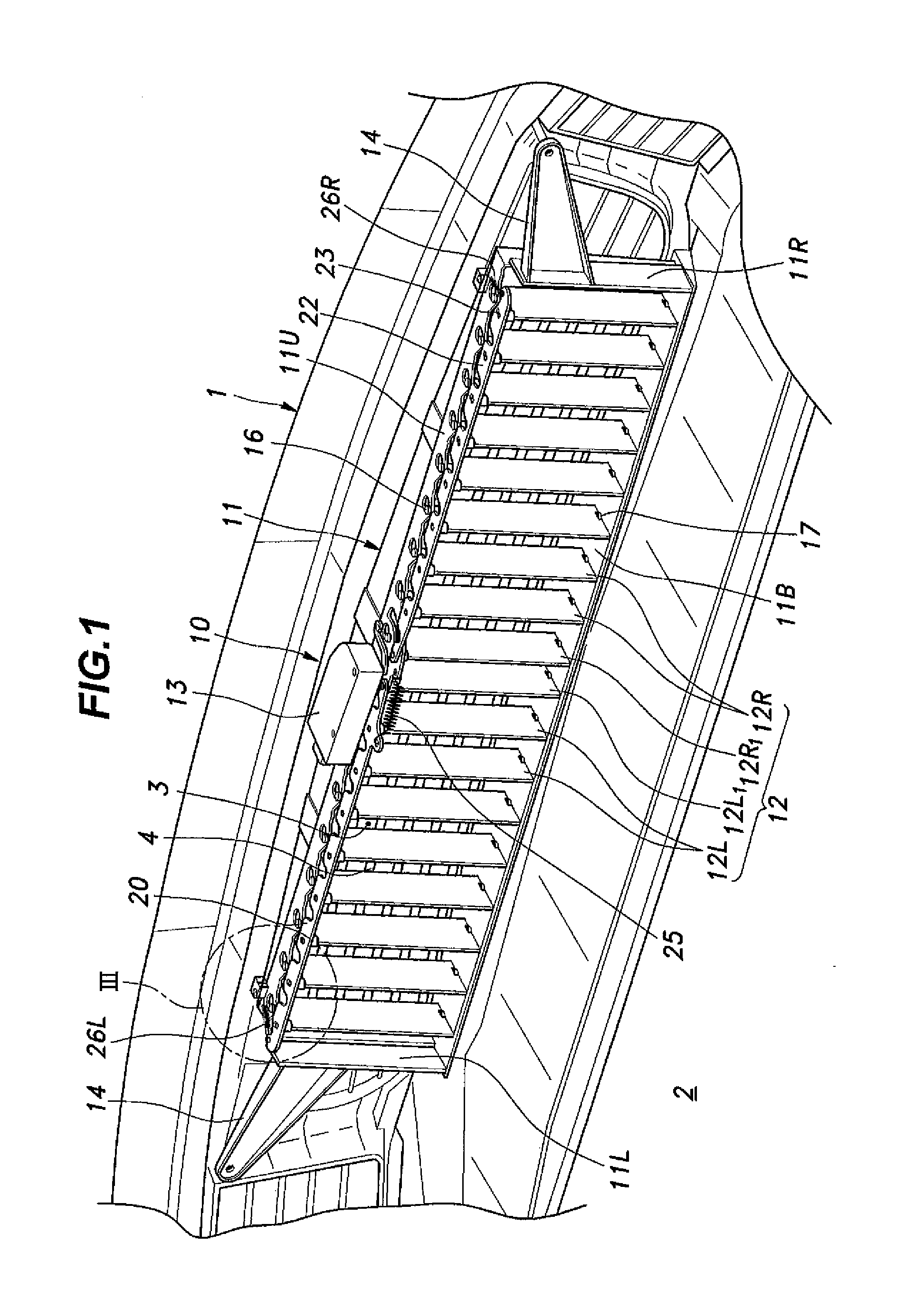
The present invention is a grill shutter that can open blades in a commercial setting despite frozen water on the blades. The invention achieves this with a drive unit that has a reduced output. The blades start opening at different times to reduce the force required for opening. This design allows for symmetrical opening of all blades and improves the commercial value of the grill shutter. Overall, the invention provides a grill shutter that can open against freezing water while using a smaller drive unit.

Problems solved by technology

In cold regions, the water adhering to the blades may freeze.
On the other hand, if the water adhering to the blade freezes with the blade being in a closed state and the drive force is insufficient to open the blades against the frozen water, the external air intake opening is kept closed, and this may result in an overheat of the engine.
Therefore, to open the closed blades against frozen water adhering to the blades, it is necessary to use a drive unit having a very large output, and this tends to increase the cost of the grill shutter.

Method used


Image

  • Grill shutter
  • Grill shutter
  • Grill shutter

Examples


first modified embodiment

[0067]Next, with reference to FIG. 10, description will be made of the first modified embodiment of the present invention. It is to be noted that the parts identical with or similar to those of the foregoing embodiment will be denoted by like numerals and redundant explanation will be omitted. This also applies to the second modified embodiment described later.

[0068]In this modified embodiment, a pair of sector gears 34L and 34R engaging each other is used instead of the S-shaped link 24 as a synchronization mechanism for operating the left-hand blades 12L and the right-hand blades 12R in synchronization. The sector gears 34L and 34R are mounted to the innermost left-hand and right-hand blades 12L1 and 12R1, respectively, such that the sector gear 34L is concentrically attached to the upper shaft 1161 of the innermost left-hand blade 12L1 and the sector gear 34R is concentrically attached to the upper shaft 1161 of the innermost right-hand blade 12R1. In this modified embodiment, an...

second modified embodiment

[0069]Next, with reference to FIG. 11, description will be made of the second modified embodiment of the present invention. In the second modified embodiment, the blades 12 are arranged substantially in parallel with a curved front edge of the external air intake opening 3 that projects forward at its lateral center, such that the blades 12 are arranged on the line that bends at the lateral center. It is to be noted that in the illustrated embodiment, the left-hand blades 12L are arranged on an oblique straight line and the left connection bar 20 has a straight shape, but the left-hand blades 12L may be arranged on a curved line and the left connection bar 20 may be curved accordingly. By arranging the blades 12 in this manner, it is possible to further reduce the size of the grill shutter 10.

[0070]In the foregoing, the present invention has been described in terms of preferred embodiments thereof. However, the present invention is not limited to the above embodiments, and various a...


PUM


Abstract

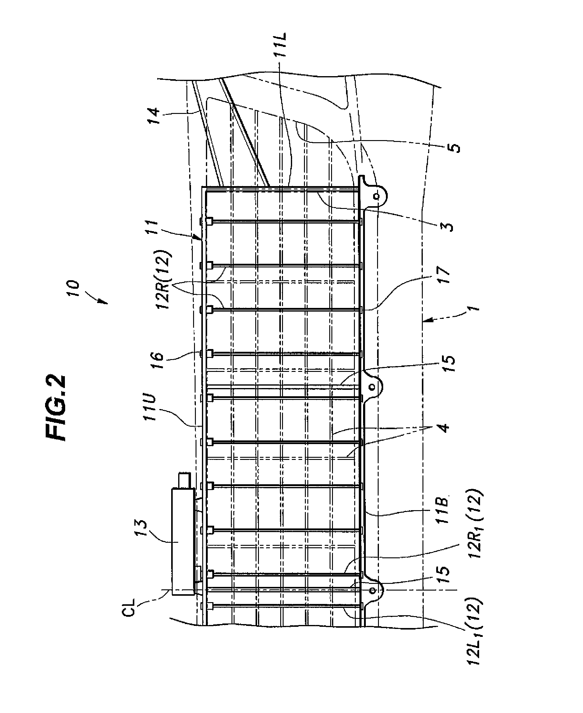
Provided is a grill shutter configured to selectively open and close an external air intake opening formed in a front part of a vehicle body. The grill shutter includes: a frame surrounding the external air intake opening; a plurality of blades rotatably supported by the frame and driven to rotate between a closed position for closing the external air intake opening and an open position for revealing the external air intake opening; a drive unit for rotationally driving the blades; and a power transmission mechanism transmitting a drive force of the drive unit to the blades, the power transmission mechanism configured to cause the blades to start an opening movement one after another with a predetermined time lag between successive opening movements.

Description

CROSS-REFERENCE TO RELATED APPLICATIONS[0001]This application claims the priority of Japanese Patent Application No. 2012-220120, filed in the Japanese Patent Office on Oct. 2, 2012, the disclosure of which is hereby incorporated by reference herein in its entirety for all purposes.TECHNICAL FIELD[0002]The present invention relates to a grill shutter for selectively opening and closing an external air intake opening formed in a front part of a vehicle body.BACKGROUND OF THE INVENTION[0003]An automobile is typically provided with an external air intake opening formed in a front part of the vehicle body to supply external air to a radiator as cooling air. In a case where the external air intake opening is covered simply by a grid-shaped grill, an airflow caused by travel of the automobile is allowed to enter the engine room at all times through the external air intake opening. However, in cold regions, the external air admitted through the external air intake opening may delay the war...

Claims


Application Information

Patent Timeline
IPC IPC(8): B60K11/08
CPCB60K11/085Y02T10/88
Inventor HIGUCHI, YYOSHITAKATASHIRO, MASAHIRO
Owner YACHIYO IND CO LTD
Learn More