Scale for rotary encoder, method of injection-molding same, and rotary encoder using same

a rotary encoder and scale technology, applied in the direction of optical conversion of sensor output, instruments, material analysis, etc., can solve the problems of difficult to improve a resolution, difficult to maintain accuracy, and difficult to stabilize the performance of the rotary encoder in individual products, so as to achieve the effect of retaining resolution

Active Publication Date: 2014-04-03
KODENSHI +1
View PDF22 Cites 1 Cited by
  • Summary
  • Abstract
  • Description
  • Claims
  • Application Information

AI Technical Summary

Benefits of technology

[0022]Thus, according to the scale for the rotary encoder of the present invention and to the rotary encoder using the same, since the light source side of the light blocking portion has a width in the radial direction set smaller than the other portions and is molded of resin so as to become separated inwardly from each radius of the first imaginary fan-shape, even if burrs are generated in the light blocking portion at the time of injection-molding of the scale or there occurs deterioration such as rounding in the die due to aged distortion and the light source side is formed larger, the variation among the individual productions can be made small while keeping high performance such as resolution almost without a change of light quantity passing through the light transmitting portion. Moreover, since the incident angle of the light passable through the scale from the light source can be made larger than the conventional one, the performance such as resolution can be retained without performing a positional alignment strictly in the circumferential direction of the light source and light detector also at the time of assembling the light source and light detector to the scale to configure the rotary encoder. Therefore, the assembly of the rotary encoder can be performed very simply.

Problems solved by technology

However, in the radial direction optical path type rotary encoder, since the scale is generally cylindrically shaped with a slit formed in a side surface portion thereof, it is difficult to maintain accuracy compared to a case of forming a slit in a flat, plate-shaped scale and it is difficult to improve a resolution.
For example, in the case where burrs are generated in this light blocking portion at the time of molding, a quantity of light allowed to pass through the light transmitting portion is varied from a designed value or a quantity of light passable through each of the light transmitting portions is varied and this results in arising a problem that performance of the rotary encoder is hard to be stabilized in individual products.
Further, a die used for molding the resin scale is deteriorated because an edge portion in the vicinity that forms the light blocking portion or light transmitting portion becomes dull or the like when the injection-molding is repeated.
In the case where deterioration such as dulling of the die occurs, new burrs which were not generated at an initial time of production are prone to generation and the light blocking portion is formed larger than the designed one, and therefore a quantity of light allowed to pass through the light transmitting portion is deviated from a designed value, which results in it being more difficult to maintain the performance such as a resolution.
In this way, in the case of drum type scales, since their shape is more complicated compared to a case of a flat, plate-shaped scale problems often occur such as burrs and the difficulty in maintaining accuracy due to deterioration of the die as mentioned above, and as a result problems occur such as the variation of performance of individual rotary encoders and difficulties with improvement of resolution of the rotary encoder itself.

Method used


Image

  • Scale for rotary encoder, method of injection-molding same, and rotary encoder using same
  • Scale for rotary encoder, method of injection-molding same, and rotary encoder using same
  • Scale for rotary encoder, method of injection-molding same, and rotary encoder using same

Examples


Embodiment Construction

[0053]The following describes one embodiment of the present invention referring to the drawings.

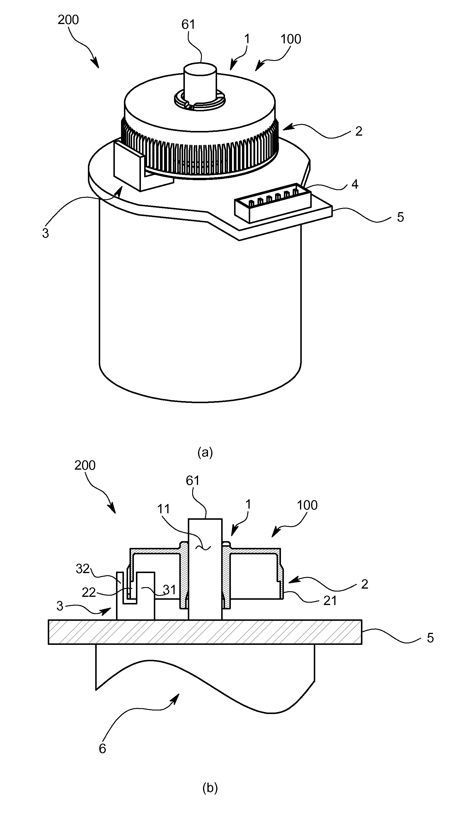
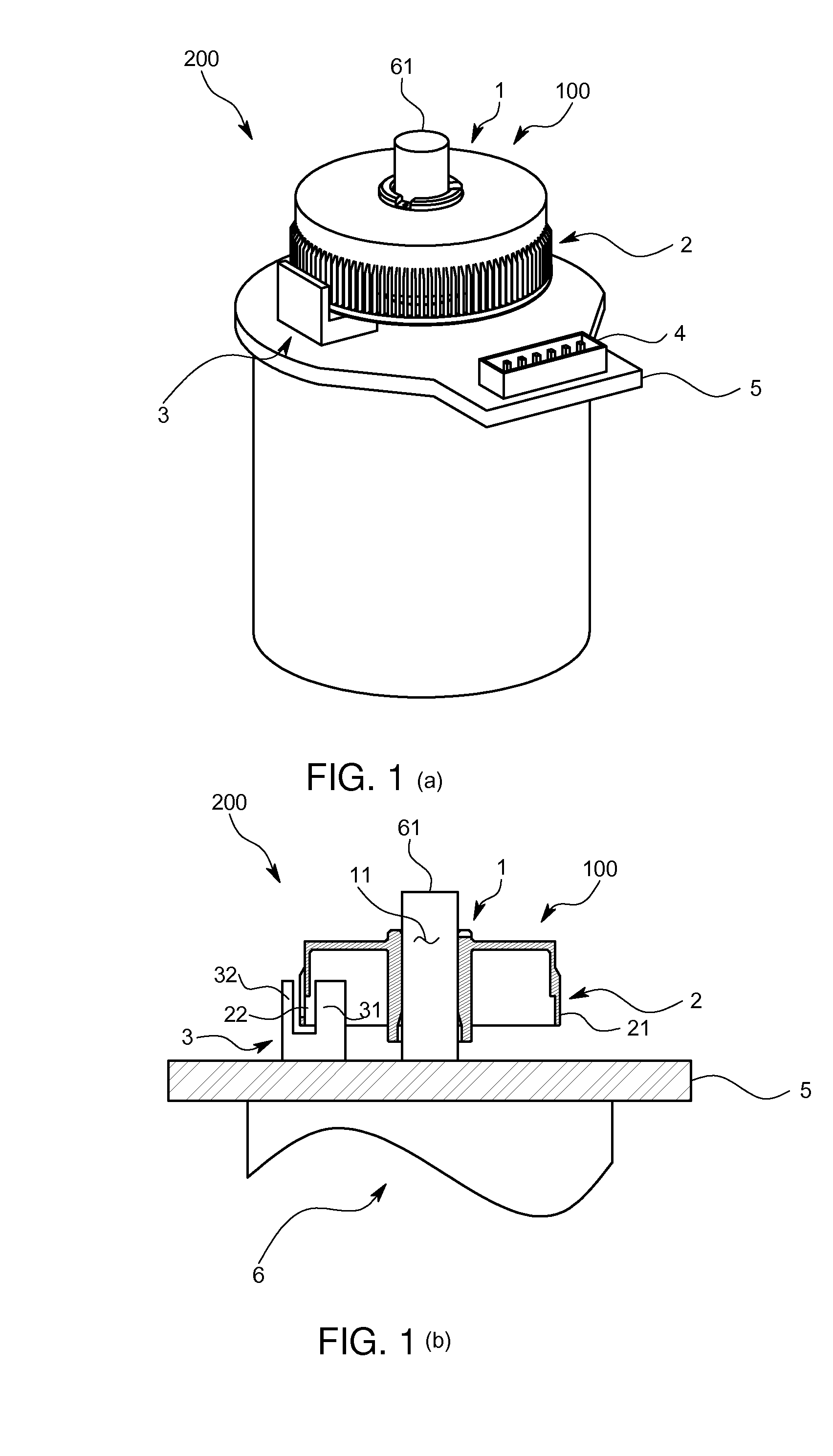
[0054]A scale 100 for a rotary encoder and a rotary encoder 200 of the present embodiment are used for detecting a rotation angle of, for example, a compact motor 6 of a printer, home electronic, or the like, and can be appropriately used for, in particular, one having a limited capacity of accommodating each piece of equipment inside thereof.

[0055]FIG. 1(a) shows a state of the rotary encoder 200 being attached to the compact motor 6 in a perspective view. The scale 100 for the rotary encoder is generally flat and cylindrically shaped as a whole with its bottom surface opened and an upper surface side fitted with an output shaft of the motor 6 and is attached so that the bottom surface thereof faces a main body side of the motor 6. In addition, the scale 100 for the rotary encoder is entirely formed of resin. Further, as shown in the perspective view of FIG. 1(a), between the scale 100 a...


PUM

PropertyMeasurementUnit
widthaaaaaaaaaa
radiusaaaaaaaaaa
length dimensionaaaaaaaaaa

Abstract

In a radial optical path type rotary encoder, in order to be able to reduce deterioration of resolution and variation among products due to burrs during molding and/or rounding of a die, a scale for a rotary encoder is provided with a scale body which is formed substantially in a cylindrical shape, the scale body having a side surface portion in which a light transmitting portion through which light passes and a light blocking portion by which light with a predetermined width in a circumferential direction is blocked are formed alternately in the circumferential direction, wherein the side surface on a light-incident side of the light blocking portion is formed outside a light transmittable region having an outer edge defined by a light beam tangent to the side surface of the light blocking portion amidst the light passing through the light transmitting portion, in a lateral cross-section view.

Description

TECHNICAL FIELD[0001]The present invention relates to a scale for use in a so-called radial direction type rotary encoder and a method of injection-molding the same.BACKGROUND ART[0002]As a rotary encoder for detecting a rotation angle of a motor, there are an axial direction optical path type one in which a flat, plate-shaped scale is fitted to a rotating shaft and an optical path between a light source and a light detector is set to the scale in the same direction as the rotating shaft, and a radial direction optical path type one in which a so-called drum type scale formed in a generally cylindrical shape with a slit formed in a side surface portion thereof is fitted to the rotating shaft and the optical path is set in the radial direction.[0003]For example, in a compact motor for use in a household printer and the like, a volume needed to install a rotary encoder on the compact motor is desired to be made as small as possible. In such an application, also as shown in Patent Docu...

Claims


Application Information

Patent Timeline
Patent Type & Authority Applications(United States)
IPC IPC(8): G01D5/347
CPCG01D5/3473G01D5/34707
Inventor FUKUDA, HIDEJISUNADA, TAKUYA
Owner KODENSHI
Why Eureka
Try Eureka