
Digital Bite Line Creation For Shoe Assembly

a technology of digital bite lines and shoe assembly, which is applied in the direction of shoe gluing, footwear, foot measurement devices, etc., can solve the problems of unsightly application of adhesives, waste, or detrimental to the performance of shoes, and approach may be costly and wasteful, and achieves sufficient resilience and pliable

Active Publication Date: 2014-04-10
NIKE INC
View PDF9 Cites 28 Cited by
  • Summary
  • Abstract
  • Description
  • Claims
  • Application Information

AI Technical Summary

Benefits of technology

The present invention is about shoes, specifically athletic shoes. These shoes are designed to protect the foot of the wearer while running, walking, or playing sports. The upper portion of the shoe is made of leather, fabric, or flexible sheets that are curved to fit the foot. The sole of the shoe has a midsole and an outsole. The midsole provides cushioning for the foot, while the outsole provides traction and durability. These shoes are often preferred by non-athletes for their comfortable fit and support.

Problems solved by technology

When using such an approach, however, care must be taken to provide sufficient adhesive coverage between the sole assembly and the upper in order to create an acceptably strong bond, but care must also be taken to avoid over application of adhesives to other regions of a shoe, such as the portions of the upper immediately above the midsole, as such an over application of adhesives can be unsightly at best and wasteful or detrimental to the performance of the shoe in some circumstances.
While meticulous and time consuming hand work coupled with a high rejection rate during quality control processes may achieve shoes with uppers and sole assemblies well adhered to one another without over application of adhesives, such an approach may be costly and wasteful.

Method used


Image

  • Digital Bite Line Creation For Shoe Assembly
  • Digital Bite Line Creation For Shoe Assembly
  • Digital Bite Line Creation For Shoe Assembly

Examples


Embodiment Construction

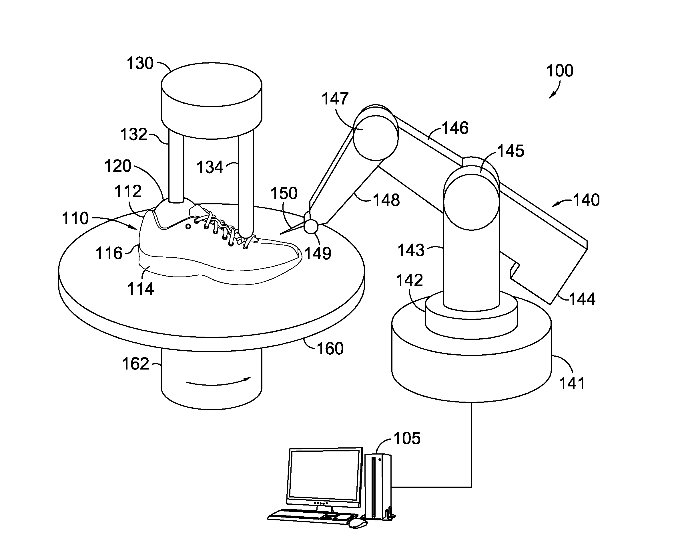
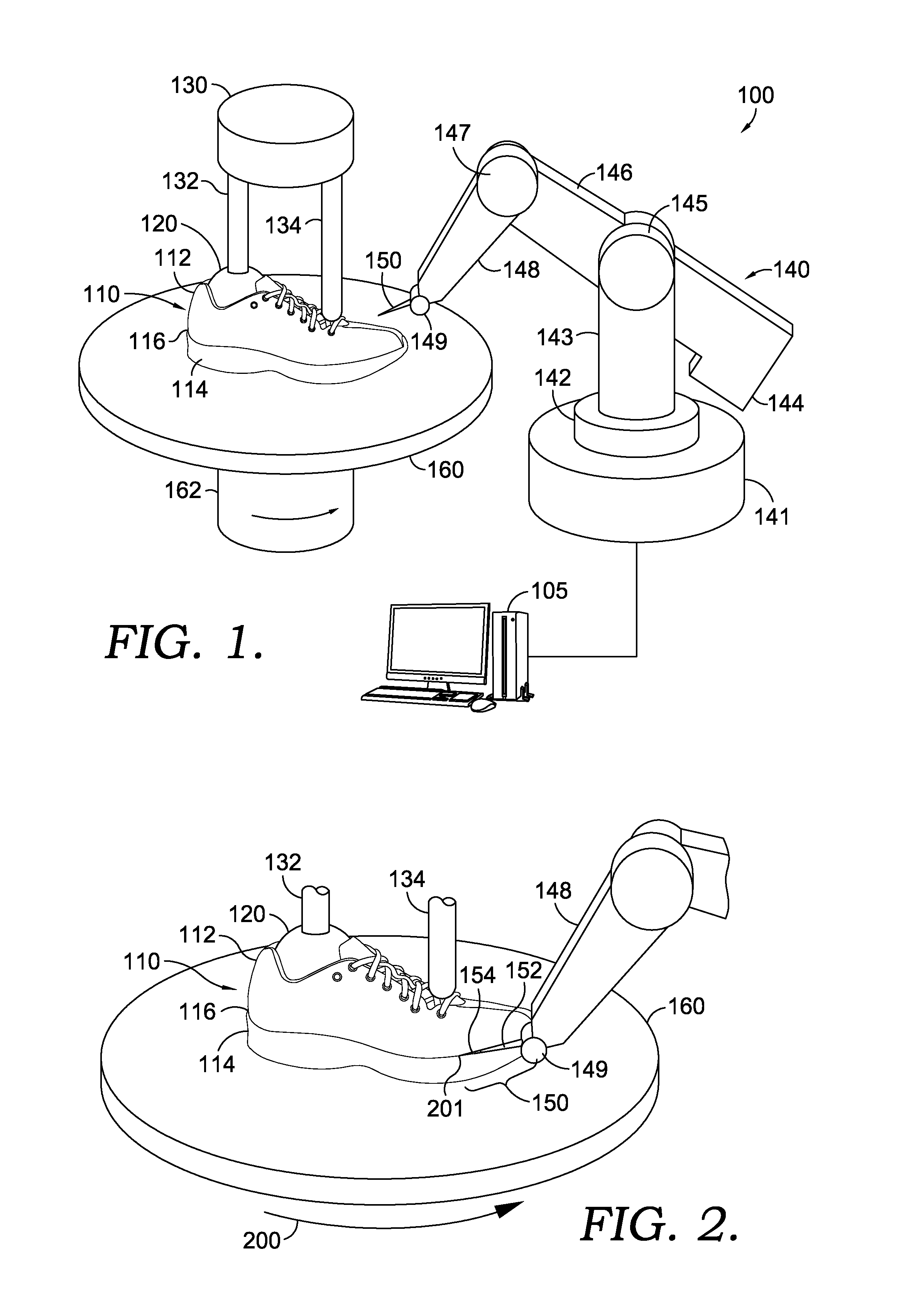
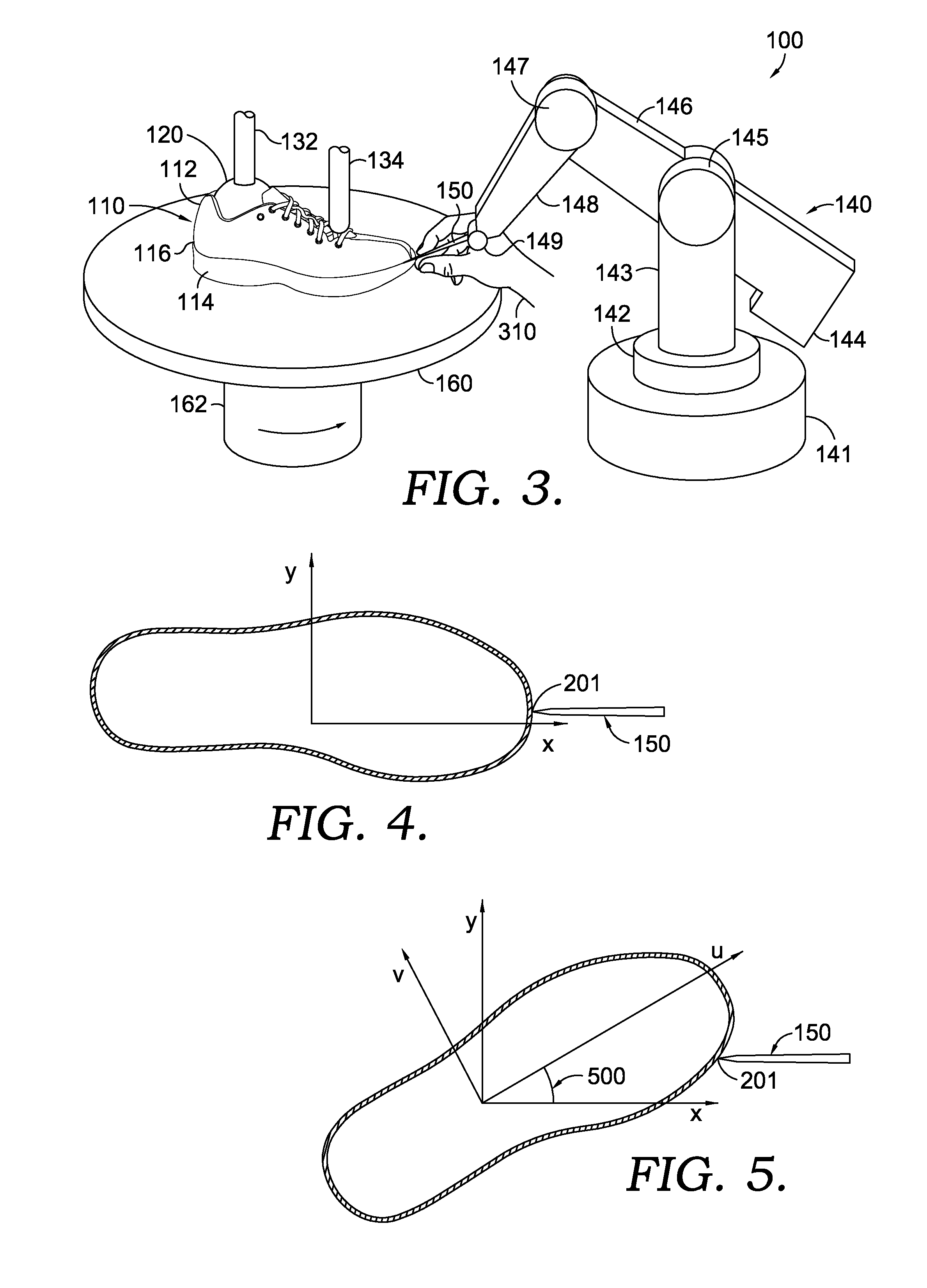
[0016]Referring now to FIG. 1, a bite line creation system 100 may comprise and arm assembly 140 terminating with a stylus 150 and a turntable assembly 160 that receives a partially assembled shoe 110. Arm assembly 140 may comprise, for example, an apparatus such as is sometimes used to create digital representations of physical objects by converting the position of a stylus, such as stylus 150, into x,y,z coordinates or an equivalent coordinate system (such as polar coordinates). For example, arm assembly 140 may be operably connected to a computer 105 such that sensors in arm assembly 140 may transmit measurements describing the position of stylus 150 to computer 105 to permit a file representing the position of stylus 150 in a three-dimensional space over a period of time. While the example arm assembly 140 illustrated in FIG. 1 is for illustrative purposes only, arm assembly 140 may comprise a base 141 having sufficient mass to provide stability for the arm assembly 140. A colla...


PUM


Abstract

A system and method may simultaneously apply a limited visibility bite line to a temporarily assembled shoe upper and shoe sole while also generating a digital bite line. The digital bite line may be used to generate a tool path for the application of adhesives to the shoe upper and / or to the shoe sole assembly to permanently assemble the shoe. The limited visibility bite line may comprise a mark or other indicia observable only under specific viewing conditions and / or only for a limited amount of time or until removal. The limited visibility bite line may be used for quality control check purposes to verify, for example, the proper application of adhesives or the proper assembly of the shoe. The limited visibility bite line may be unobservable to the ultimate purchaser and / or wearer of the shoe.

Description

CROSS-REFERENCE TO RELATED APPLICATIONS[0001]Not applicable.STATEMENT REGARDING FEDERALLY SPONSORED RESEARCH OR DEVELOPMENT[0002]Not applicable.TECHNICAL FIELD[0003]The present invention relates to a system and method for generating bite lines for the assembly of shoes. More particularly, the present invention relates to a system and method for creating a digital bite line for use in applying adhesives as part of the assembly of a shoe upper to a shoe sole assembly and to creating limited visibility bite lines for use in quality control checking during the manufacturing of shoes.BACKGROUND OF THE INVENTION[0004]Shoes may be made by combining components, such as uppers and soles, which may themselves be made of sub-components. Various techniques, such as stitching and / or applying adhesives may be used to combine the components and / or sub-components of a shoe into a finished product. Whatever technique is used to join components and / or sub-components during the assembly of a shoe, tho...

Claims


Application Information

Patent Timeline
IPC IPC(8): A43D1/08
CPCA43D1/08A43D25/18A43D2200/60A43D8/00A43D25/06A43D8/26
Inventor REGAN, PATRICK CONALLCHANG, CHIH-CHIJEAN, MING-FENG
Owner NIKE INC
Learn More