Tire pressure maintenance device

a tire pressure maintenance and tire technology, applied in the direction of tire measurement, vehicle components, transportation and packaging, etc., can solve the problems of tens of thousands of injuries, hundreds of deaths, and dangerous under-inflation of vehicle tires, and achieve the effects of reducing the risk of under-inflation, reducing the risk of injury, and reducing the safety of drivers

Inactive Publication Date: 2014-04-10
LOEWE RICHARD
View PDF8 Cites 17 Cited by
  • Summary
  • Abstract
  • Description
  • Claims
  • Application Information

AI Technical Summary

Benefits of technology

[0019]A new device automatically maintains a desired inflation pressure of an interior of a tire mounted on a wheel of a vehicle and overcomes normal car tire leakage. A magnetic element is attached to a stationary part of a wheel assembly and a compressor, such as a microcompressor, is mounted on the rotating wheel. The compressor is magnetically activated as it passes near the magnetic element. The magnetic element, which may be a stationary permanent magnet or electromagnet, may thus be used as the driving element, and several magnetically-driven compressor configurations are disclosed herein. The compressor may perform at least one cycle per wheel revolution. Alternatively, an electrical coil can be mounted on the wheel to pass near the magnetic element, thereby inducing voltage pulses in the coil to provide on-wheel electrical power to run an electrically-driven compressor that is mounted at another location on the wheel.

Problems solved by technology

Under-inflation of vehicle tires is dangerous, deadly and common.
Under-inflation is involved in hundreds of thousands of accidents, tens of thousands of injuries and hundreds of fatalities annually in the United States.
During 2000, a large number of SUV rollovers and deaths were attributed to significantly under-inflated tires, bringing significant attention to the problem.
The program is estimated to cost well over one billion dollars annually.
However, even if the controversial TPMS program achieves its estimates it will reduce under-inflation related accidents by only about twenty percent.
Many industry experts doubt that it will help at all.
Most under-inflation is due to inadequate manual tire pressure maintenance.
None of these approaches address temperature variation significantly.
One such approach involves a difficult generation of two continuous out of phase AC voltages that are rectified to provide a continuous DC power source for a DC motor-driven air compressor on the wheel.
Another approach discloses a battery-operated compressor contained on a wheel with no practical means for recharging the battery.
However, none of these approaches have produced a practical device.

Method used


Image

  • Tire pressure maintenance device
  • Tire pressure maintenance device
  • Tire pressure maintenance device

Examples


Embodiment Construction

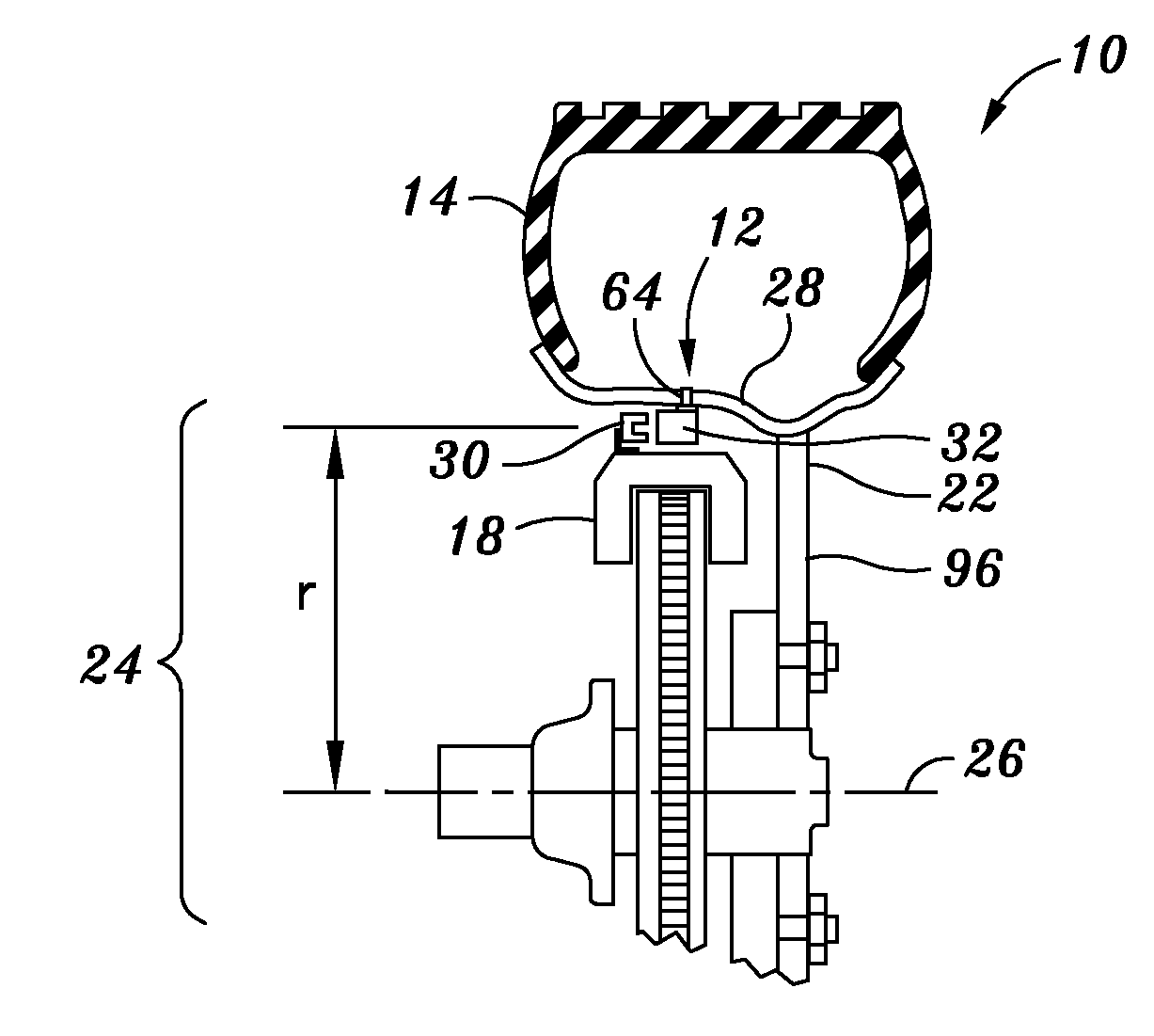
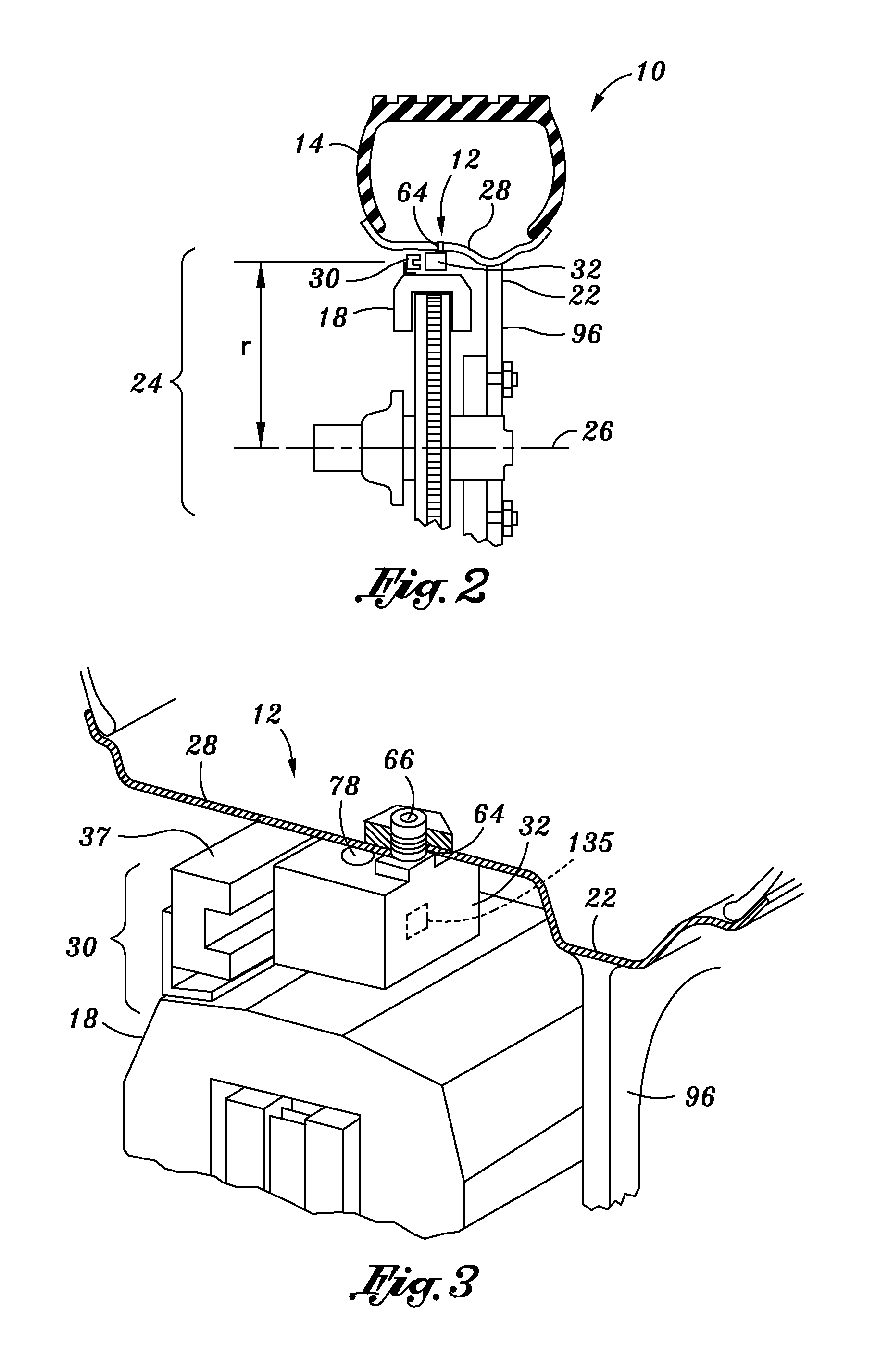
[0051]Referring now to the drawings wherein the showings are for purposes of illustrating the various embodiments of the present invention and not for purposes of limiting the same, FIG. 2 is a cross-section view of a partial automobile wheel assembly 10 and a device 12 for maintaining a desired inflation pressure of an interior of a tire 14 by using the rotation of the wheel 22 with respect to the wheel assembly 10. As is known in the art, various configurations exist for wheel assemblies 10. A wheel assembly 10 is generally movably attached to a vehicle frame by a suspension and in some cases, by a steering mechanism. For simplicity, the embodiments of the present invention will be discussed with reference to generic elements that are commonly present in most wheel assemblies 10. However, as will be understood, implementations of the present invention may be retrofitted into a variety of existing wheel assemblies 10 or designed into new wheel assemblies 10 of differing configurati...


PUM


Abstract

A device for maintaining a desired inflation pressure within a tire mounted on a wheel of a vehicle which includes a flexible compression chamber and a magnetic element not on the wheel. As the compressor passes the magnet each wheel revolution, a small amount of atmospheric air is pumped into the tire, if needed. The magnet and the compressor need no other contact with the vehicle or the wheel and require no energy source on the wheel.

Description

CROSS-REFERENCE TO RELATED APPLICATIONS[0001]This application is a continuation-in-part of U.S. application Ser. No. 11 / 711,398, filed on Feb. 27, 2008 which is a continuation-in-part of U.S. application Ser. No. 11 / 273,116 filed Nov. 14, 2005, the contents of which are wholly incorporated by reference herein and which claims priority to provisional application Ser. No. 60 / 627,256 filed on Nov. 12, 2004.STATEMENT RE: FEDERALLY SPONSORED RESEARCH / DEVELOPMENT[0002]Not ApplicableBACKGROUND[0003]The present invention relates generally to vehicle tire pressure maintenance, and more specifically, to a tire pressure maintenance device contained on a wheel of a vehicle that automatically regulates and maintains a desired tire inflation pressure or amount of air in a tire.[0004]Under-inflation of vehicle tires is dangerous, deadly and common. Under-inflation is involved in hundreds of thousands of accidents, tens of thousands of injuries and hundreds of fatalities annually in the United Stat...

Claims


Application Information

Patent Timeline
Patent Type & Authority Applications(United States)
IPC IPC(8): B60C29/00
CPCB60C23/0408B60C23/133B60C23/126B60C23/129
Inventor LOEWE, RICHARD
Owner LOEWE RICHARD
Why Eureka
Try Eureka