
Image producing apparatus and image producing method

a technology of image producing apparatus and image, which is applied in the direction of printing, other printing apparatus, etc., can solve the problems of poor image quality and appearance, and the inkjet image producing apparatus tends to suffer from problems, so as to reduce the quality and appearance of an image

Active Publication Date: 2014-04-10
FUJIFILM CORP
View PDF2 Cites 3 Cited by
  • Summary
  • Abstract
  • Description
  • Claims
  • Application Information

AI Technical Summary

Benefits of technology

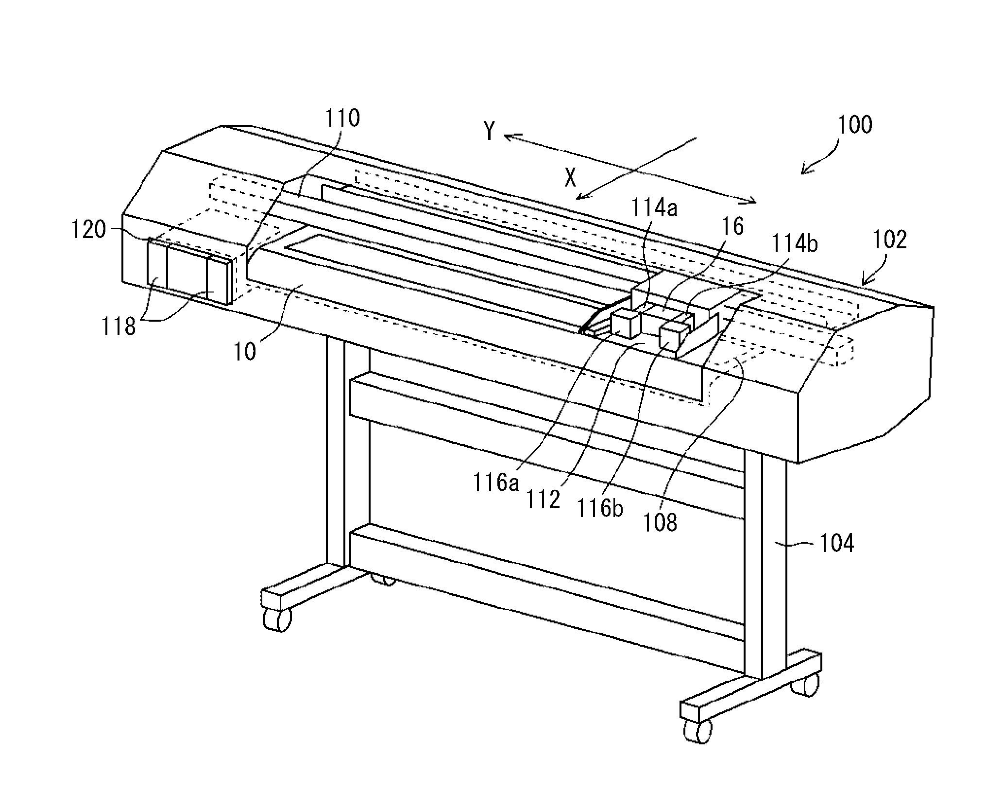
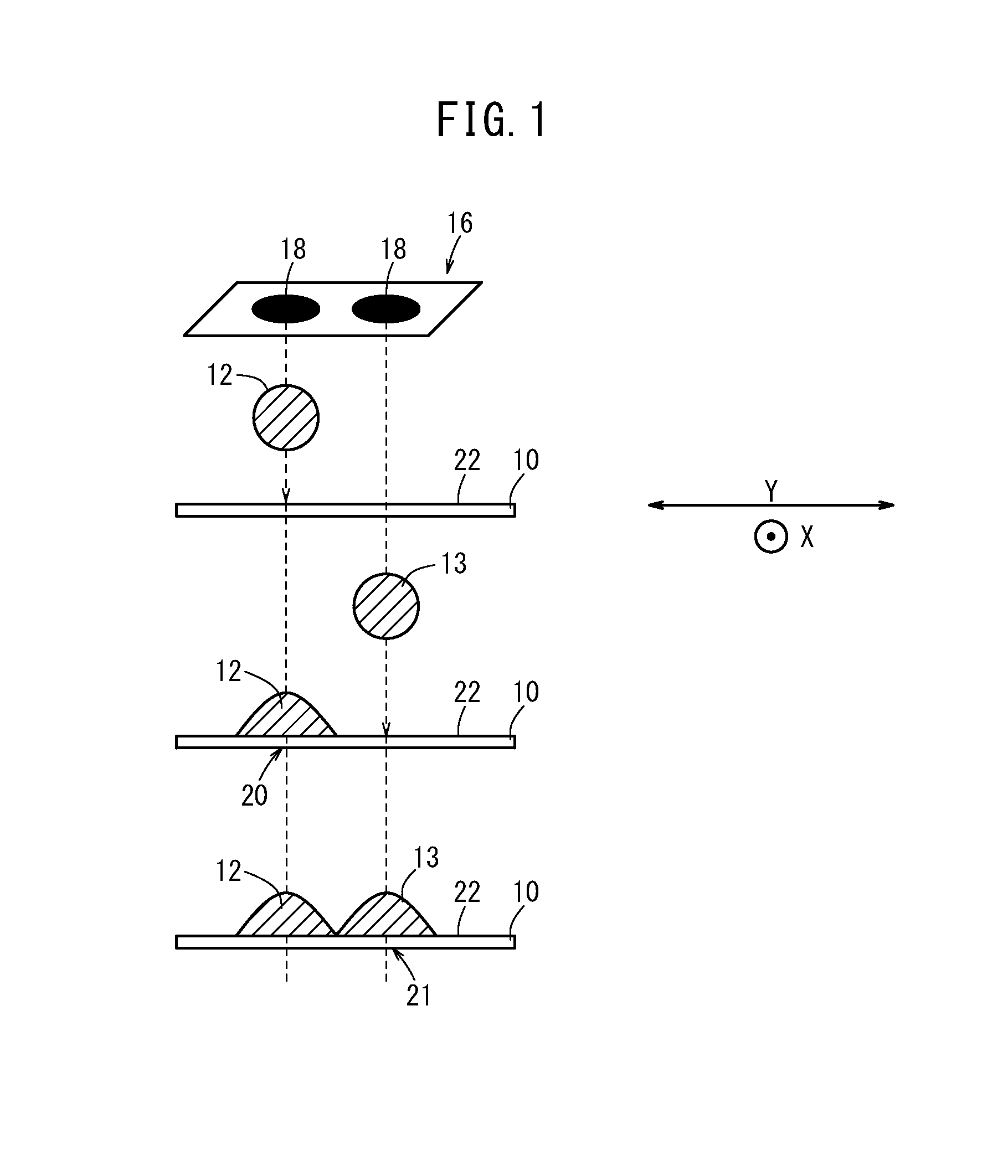
The present invention is about an image producing apparatus and method that can prevent poor image quality and appearance caused by interference between deposited ink droplets. By classifying dots formed along the transverse direction into plural groups and controlling the timing of ejection, preceding dots formed in a pale color help hold subsequently deposited ink droplets and prevent them from shifting or interfering with other dots. This results in improved image quality and appearance, minimizing adverse effects caused by interference between the ink droplets.

Problems solved by technology

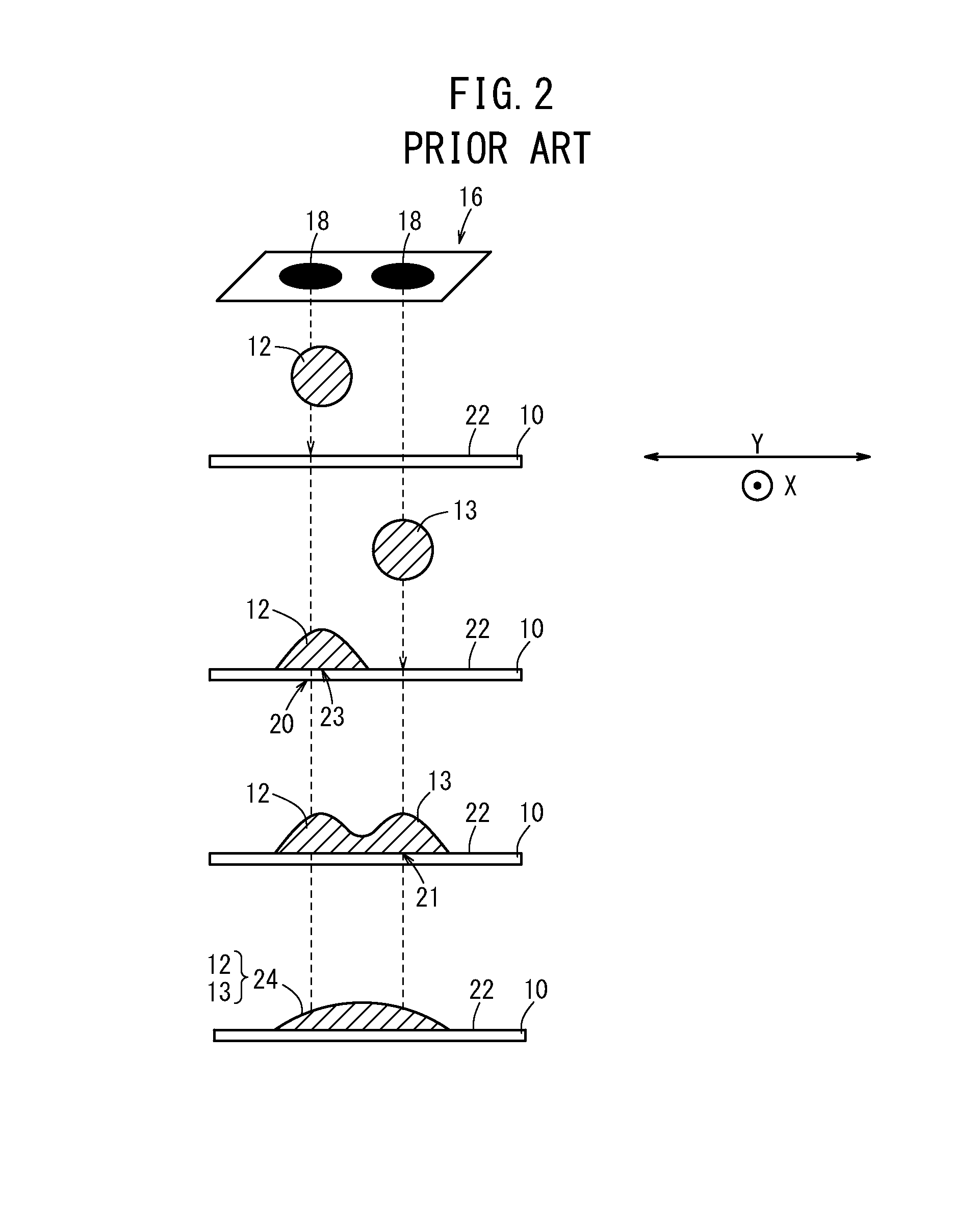
If an inkjet image producing apparatus is designed to produce images at higher speeds and to achieve a higher density of dots, then the inkjet image producing apparatus tends to suffer from problems due to interference between ink droplets that are deposited on the recording medium.
Since at this time the center of gravity of the dot formed by the subsequent ink droplet is displaced, the resultant image is likely to suffer from low granularity and gloss irregularities, resulting in poor image quality and appearance.

Method used


Image

  • Image producing apparatus and image producing method
  • Image producing apparatus and image producing method
  • Image producing apparatus and image producing method

Examples


first embodiment

[Modifications of First Embodiment]

[0083]According to the first embodiment, the transparent color (clear: CL) is used as a pale color. However, a non-transparent (chromatic) color including gray (Gy), light cyan (LC), light magenta (LM), or yellow (Y) may be used as a pale color.

[0084]According to the first embodiment, no particular size has been specified in relation to the preceding dots 66. However, any desired size may be selected for the preceding dots 66. In particular, if the recording head 16 is capable of forming dots having two or more sizes, then it is preferable to select a minimal size for the preceding dots 66, taking into consideration both image quality and cost, insofar as the preceding dots 66 serve as anchors for holding the ink droplets 12.

[0085]A setting for judging whether or not preceding dots 66 should be formed may be made either manually by the operator or automatically depending on attributes of a content image to be printed. Alternatively, if a monochroma...

second embodiment

[Modifications of Second Embodiment]

[0106]In the second embodiment, it is necessary, physically or by means of a control process, to produce a difference between the times at which the preceding dots 80 and the dots 86 are formed. Therefore, the nozzles 18 that expel the ink droplets 12, etc., in a pale color may be disposed upstream of the nozzles 18 that expel the ink droplets 12, etc., in a deep color with respect to the direction of the arrow X. In other words, the recording head 16 is not limited to the structures shown in FIGS. 11A and 11B, but may have the structure described below.

[0107]As shown in FIG. 14, head modules 16LC, 16C have unit heads 90LC, 90C, each of which includes a one-dimensional array of nozzles 18, the number and pitch of which are the same for all of the unit heads 90LC, 90C.

[0108]More specifically, the head module 16LC comprises a pair of short unit heads 90LC, 90LC, which are disposed in a staggered pattern having edges joined to each other. The head mo...


PUM


Abstract

A control signal is generated, so that if dots, which are formed in a transverse direction across a recording medium, are classified into plural groups depending on a plurality of timings, then preceding dots, which belong to a group having an earliest timing, are formed in a pale color. A head drive circuit controls a recording head based on the generated control signal.

Description

CROSS-REFERENCE TO RELATED APPLICATION[0001]This application is based upon and claims the benefit of priority from Japanese Patent Application No. 2012-223665 filed on Oct. 5, 2012, the contents of which are incorporated herein by reference.BACKGROUND OF THE INVENTION[0002]1. Field of the Invention[0003]The present invention relates to an image producing apparatus and an image producing method for producing an image by forming dots in a plurality of colors on a recording medium.[0004]2. Description of the Related Art[0005]With significant advances in inkjet technology in recent years, it is becoming possible for inkjet image producing apparatus to produce large color prints of high quality at high speeds. Inkjet image producing apparatus are widely used particularly in sign and display applications, and are applicable to, for example, prints on POP (Point Of Purchase) posters, wall posters, outdoor advertisements, billboards, etc. Such inkjet image producing apparatus are capable of...

Claims


Application Information

Patent Timeline
IPC IPC(8): B41J2/07
CPCB41J2/07B41J2/175B41J29/38B41J2/2114B41J2/2121B41J2/2054B41J2/2132
Inventor MISHIMA, TAKAHIRO
Owner FUJIFILM CORP
Learn More