
Method to control a minimum pulsewidth in a switch mode power supply

Active Publication Date: 2014-04-10
MYPAQ HLDG LTD
View PDF8 Cites 10 Cited by
  • Summary
  • Abstract
  • Description
  • Claims
  • Application Information

AI Technical Summary

Benefits of technology

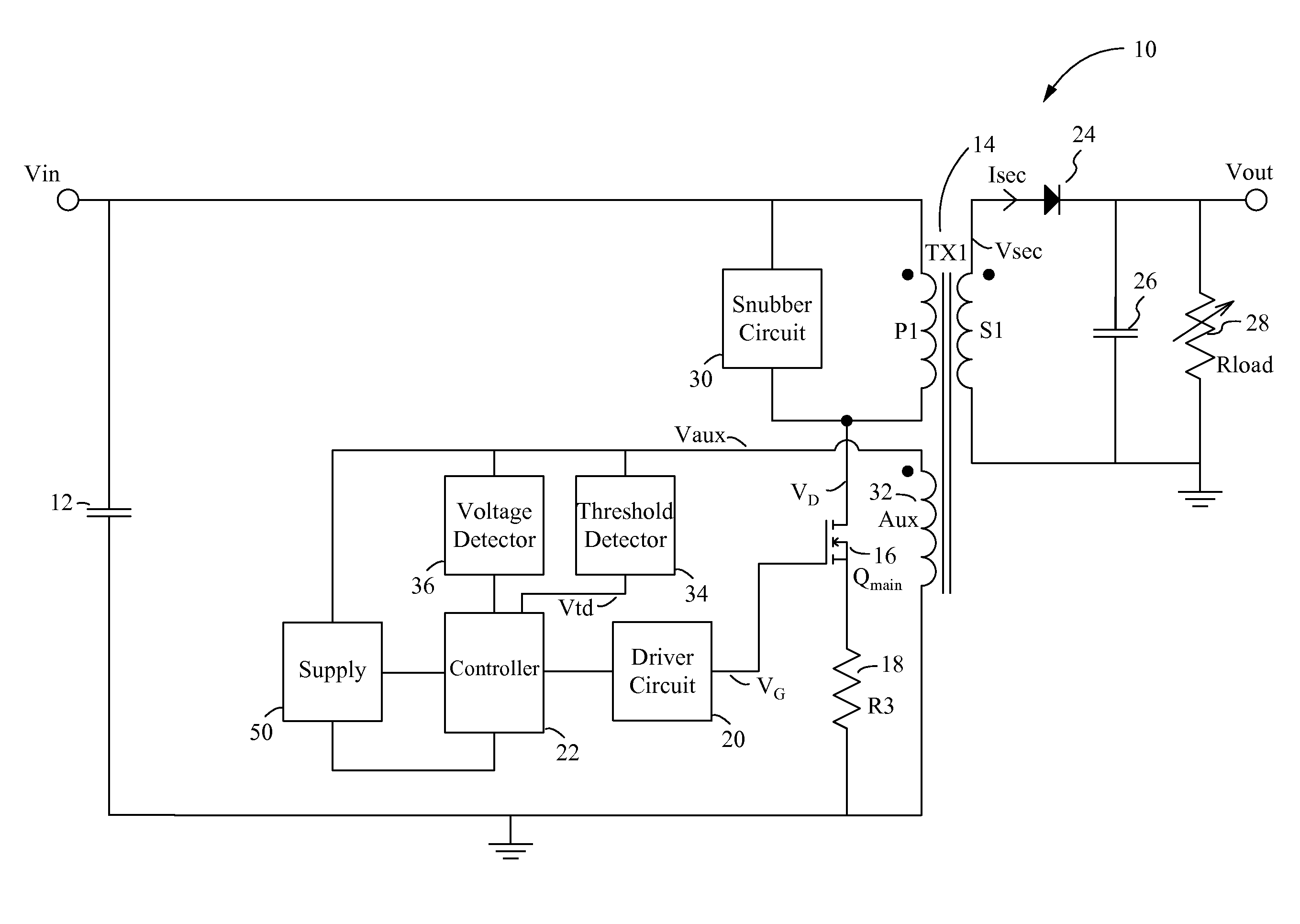
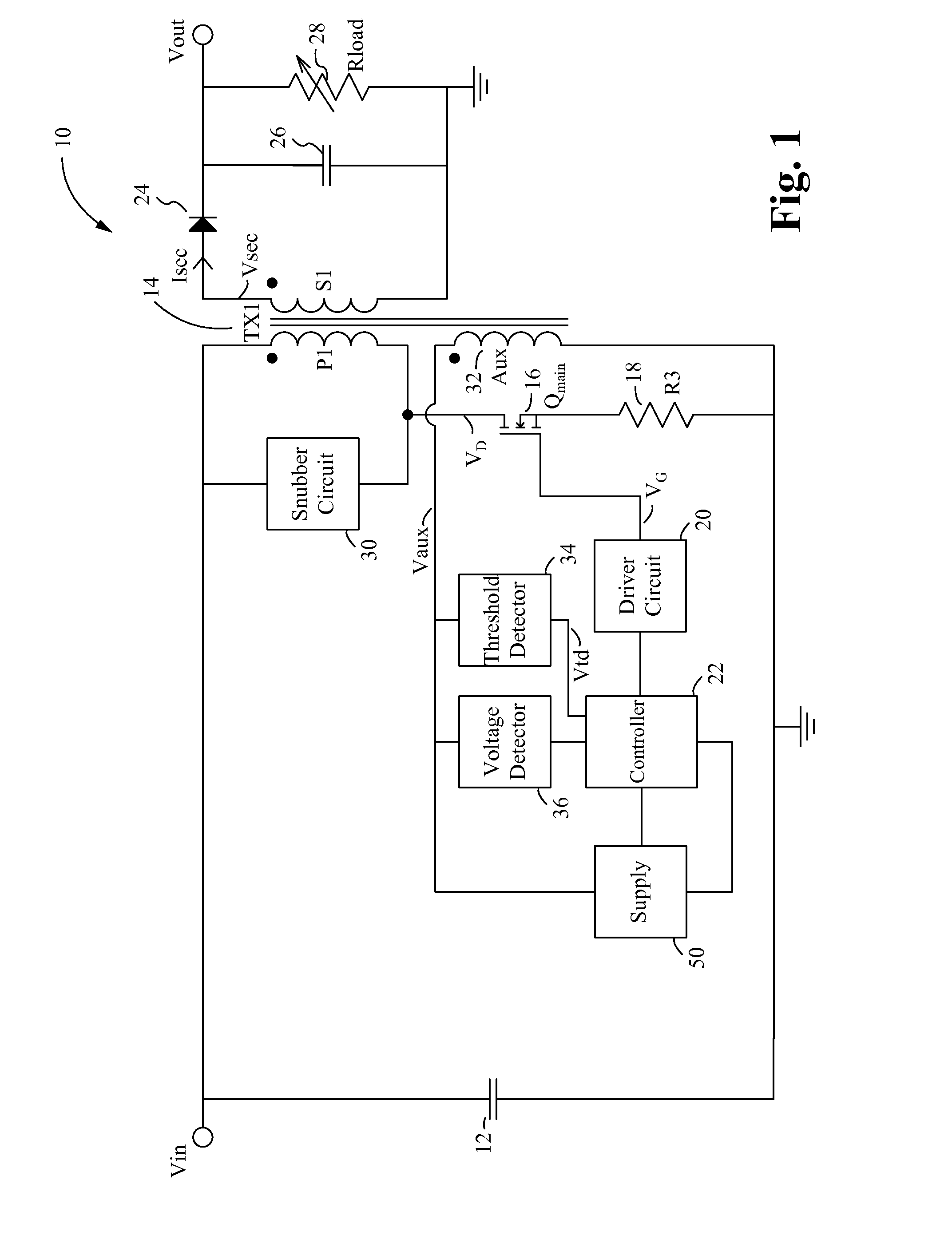
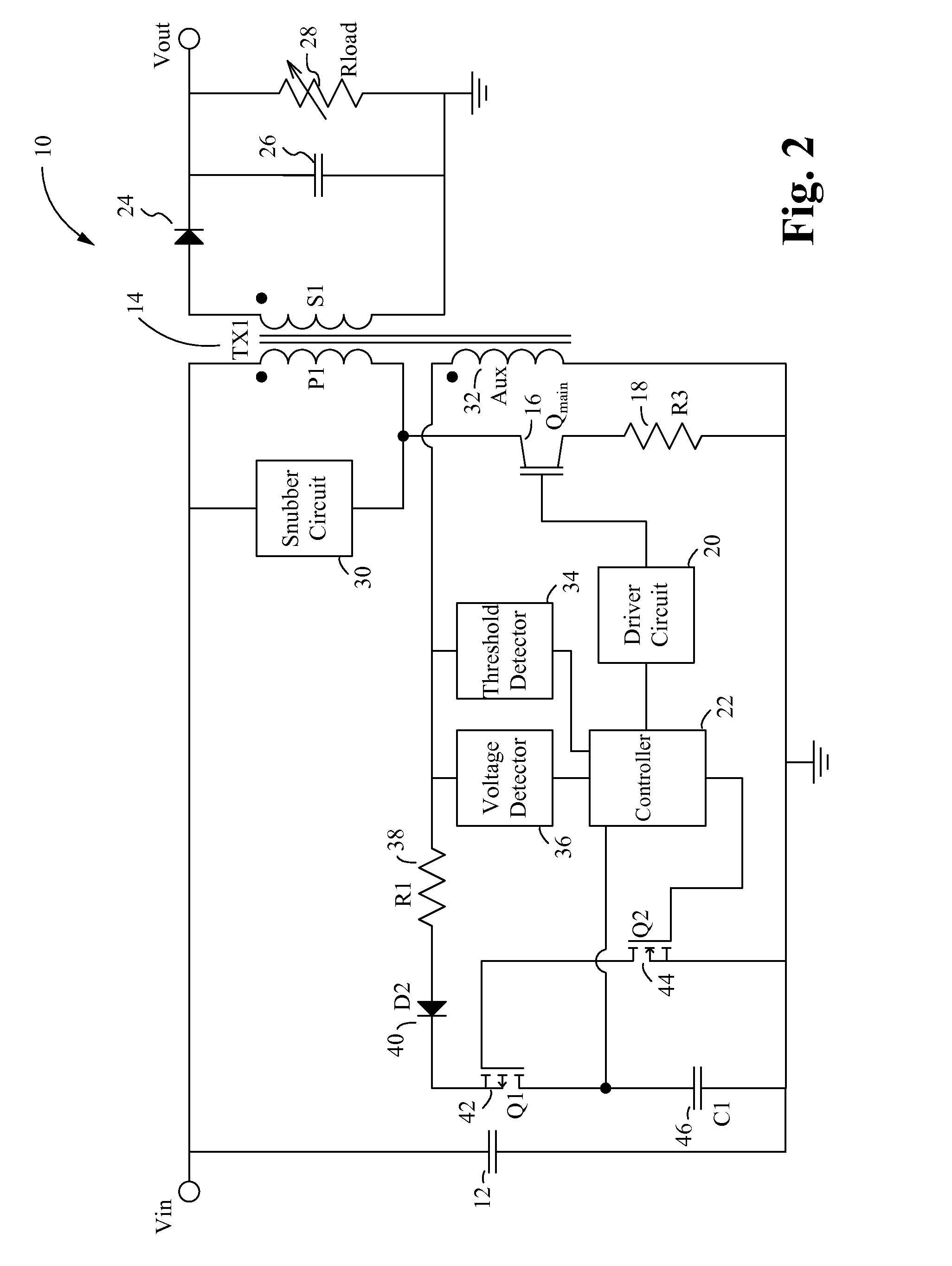
The patent is about a power converter circuit and method that reduces the amount of energy transferred to the secondary side of the circuit while still maintaining a minimum amount of energy transfer to enable output voltage sensing. This is achieved by using a transformer and a main switch controlled by a driving circuit. A sensing circuit is also implemented to control the amount of energy transfer by sensing the voltage at an auxiliary winding of the transformer. By setting a threshold voltage level, the amount of energy transferred per pulse is minimized while maintaining a minimum amount of energy transfer to enable output voltage sensing.

Problems solved by technology

Very low switching frequency has the disadvantage that voltage sensing via a winding of the transformer is very slow.
It is very difficult to control the on time precisely enough such that the energy transfer is minimized, but still big enough to have a small amount of energy transferred to the secondary side without direct feedback.
If the pulse is too small, all of the energy is lost in parasitic elements.

Method used


Image

  • Method to control a minimum pulsewidth in a switch mode power supply
  • Method to control a minimum pulsewidth in a switch mode power supply
  • Method to control a minimum pulsewidth in a switch mode power supply

Examples


Embodiment Construction

[0021]Embodiments of the present application are directed to a power converter. Those of ordinary skill in the art will realize that the following detailed description of the power converter is illustrative only and is not intended to be in any way limiting. Other embodiments of the power converter will readily suggest themselves to such skilled persons having the benefit of this disclosure.

[0022]Reference will now be made in detail to implementations of the power converter as illustrated in the accompanying drawings. The same reference indicators will be used throughout the drawings and the following detailed description to refer to the same or like parts. In the interest of clarity, not all of the routine features of the implementations described herein are shown and described. It will, of course, be appreciated that in the development of any such actual implementation, numerous implementation-specific decisions must be made in order to achieve the developer's specific goals, such...


PUM


Abstract

A power converter circuit includes a transformer and a main switch controller by a primary side controller. A sensing circuit is implemented that senses the voltage at an auxiliary winding of the transformer while the main switch is ON. The auxiliary winding is another winding on the primary side of the transformer, magnetically coupled to the secondary winding and electrically isolated from the primary winding. When the voltage across the auxiliary winding reaches a predefined threshold voltage level, the main switch is switched OFF. The threshold voltage level is set at a value that minimizes an amount of energy transferred per pulse to the secondary side of the circuit while maintaining a minimum amount of energy transfer to enable output voltage sensing at the auxiliary winding.

Description

RELATED APPLICATIONS[0001]This Patent Application claims priority under 35 U.S.C. 119 (e) of the co-pending U.S. provisional application, Ser. No. 61 / 712,183, filed Oct. 10, 2012, and entitled “Intermediate Valley Switching Mode Converter”, by this same inventor. This application incorporates U.S. provisional application, Ser. No. 61 / 712,183 in its entirety by reference.FIELD OF THE INVENTION[0002]The present invention is generally directed to the field of power converters. More specifically, the present invention is directed to a new power converter architecture having increased efficiency.BACKGROUND OF THE INVENTION[0003]A power supply or power converter converts one form and voltage of electrical power to another desired form and voltage. AC-to-DC power supplies convert alternating current voltage, for example 115 or 230 volt alternating current (AC) supplied by a utility company, to a regulated direct current (DC) voltage. DC-to-DC power supplies convert DC voltage at one level,...

Claims


Application Information

Patent Timeline
IPC IPC(8): H02M3/335H02M1/00
CPCH02M3/33546H02M3/33523H02M3/33553Y02B70/10H02M1/0003H02M1/0032H02M3/335H02M3/33538
Inventor SCHROEDER GEN BERGHEGGER, RALF
Owner MYPAQ HLDG LTD
Learn More