
Devices and methods for performing cpr while standing up

Inactive Publication Date: 2014-04-10
PHYSIO CONTROL INC
View PDF17 Cites 6 Cited by
  • Summary
  • Abstract
  • Description
  • Claims
  • Application Information

AI Technical Summary

Benefits of technology

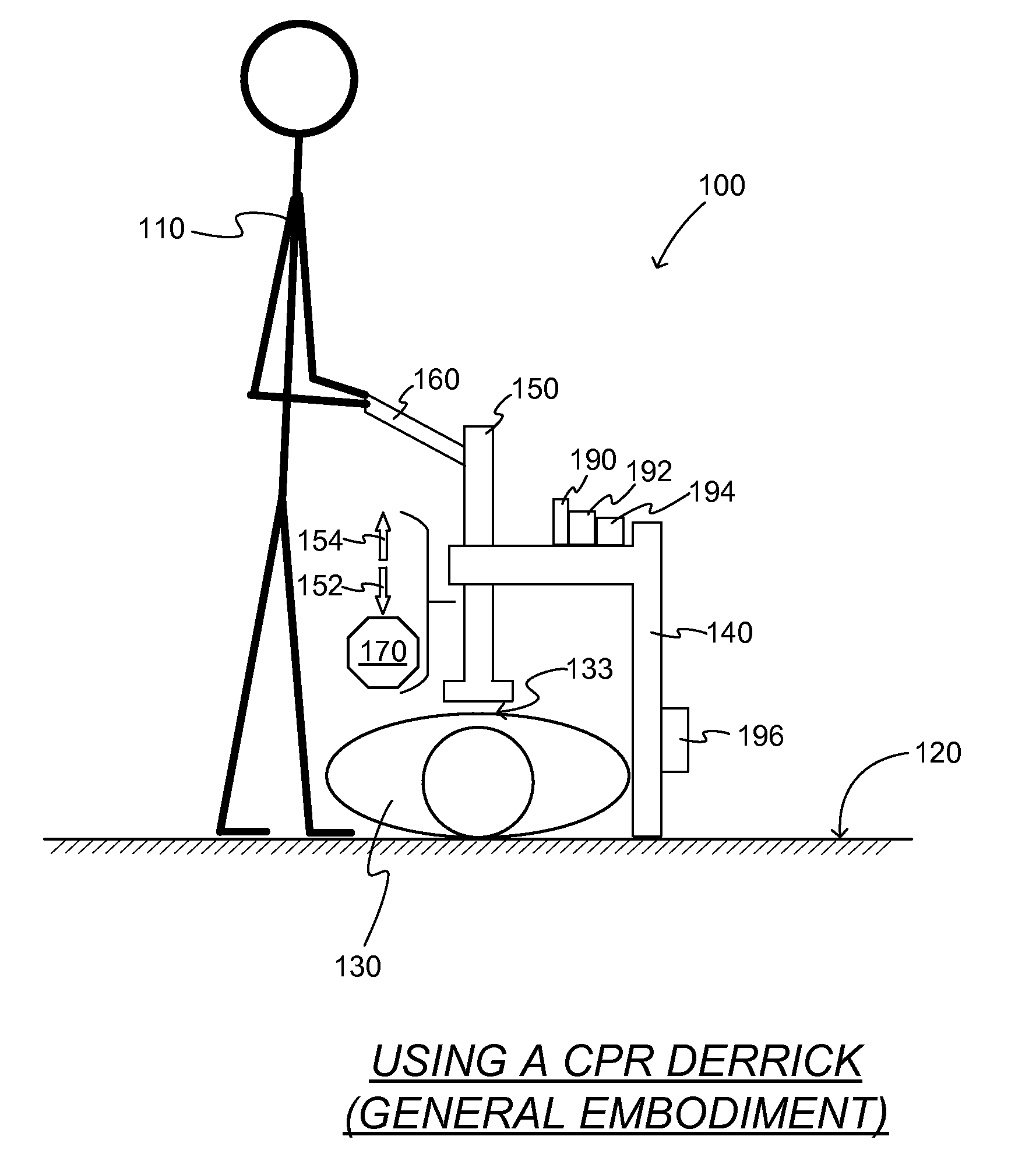
The invention is a device called a CPR derrick that allows first responders to perform CPR chest compressions while standing up, without having to kneel. Standing up is easier on the knees and allows the rescuer to provide higher quality CPR for a longer time, giving more opportunity for a life-saving team to arrive in time. This device can be used by trained first responders, firemen, and EMS personnel, and can also be useful for people who may lack the strength or endurance to provide traditional CPR.

Problems solved by technology

CPR may have to be performed for a long time, before competent help arrives.
However, rescuer fatigue often prevents CPR chest compressions from being performed correctly for a long time, at least in the traditional way.
After some time, the rescuer's knees will start to hurt.
Moreover, to perform a good release after each compression, the rescuer often has to lift his torso by the waist, while the torso is in near horizontal position, which is also tiring.

Method used


Image

  • Devices and methods for performing cpr while standing up
  • Devices and methods for performing cpr while standing up
  • Devices and methods for performing cpr while standing up

Examples


embodiment 200

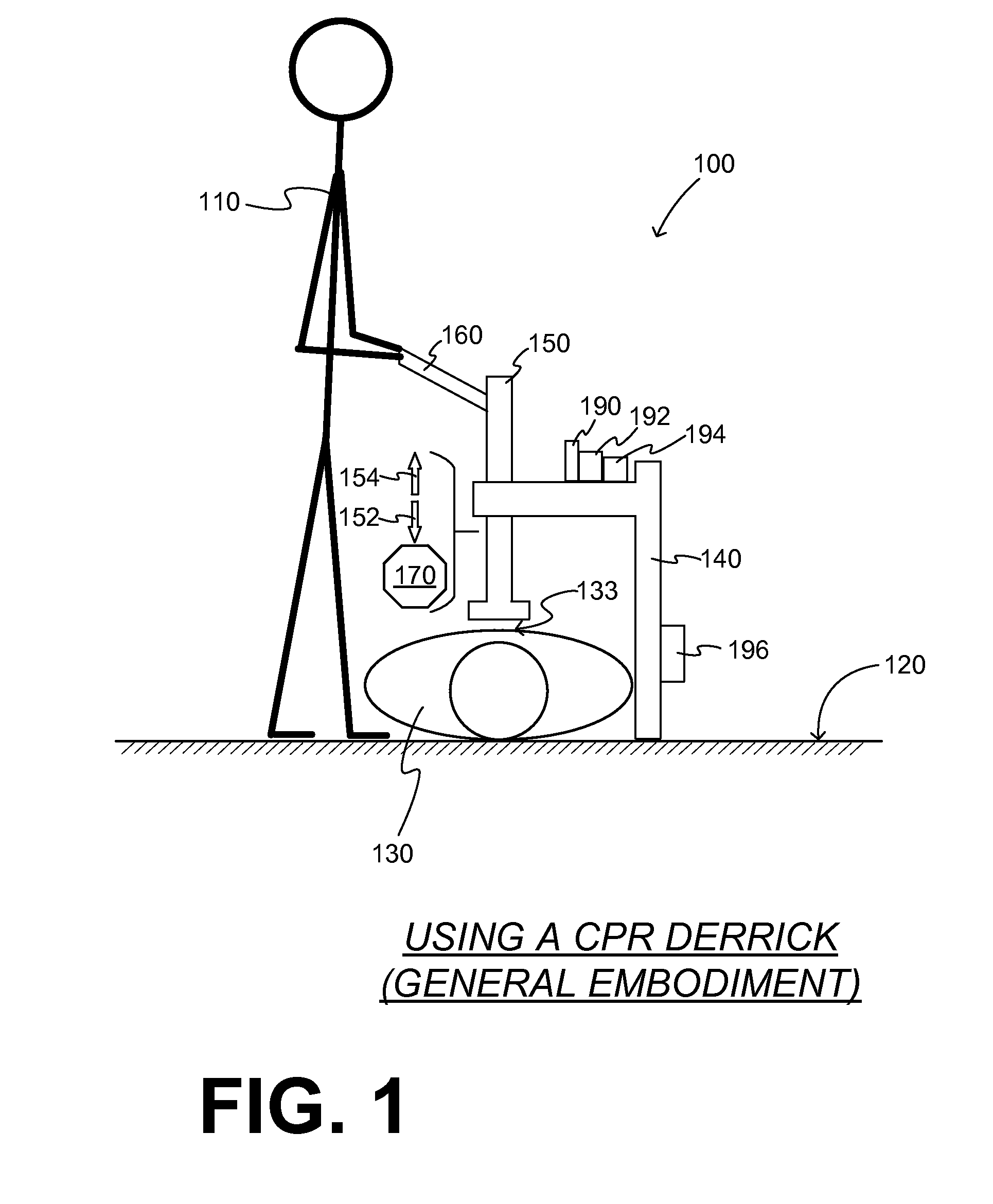
[0054]Embodiment 200 also includes a piston 250, and an actuator 260 that is a handle. The handle can be moved up and down, which causes piston 250 to perform the up motions and the down motions. This is an example of an actuator that is retained substantially horizontal with respect to horizontal surface 120 for its manual operation through many of the cycles.

[0055]The embodiment of FIG. 2 is also an example of where the actuator is operated by being moved in two substantially opposite directions, at the same frequency as the up and down motions. Other embodiments are also possible. For example, a second actuator can be further provided, which can be moved in unison or not with the first. For another example, a wheel or flywheel could be provided with gear. The actuator can be one or more handles or pedals for causing the wheel to spin, and the spinning wheel in turn causes, via the gear, the piston to perform the down and up motions.

[0056]Embodiment 200 further includes a bottom s...

embodiment 300

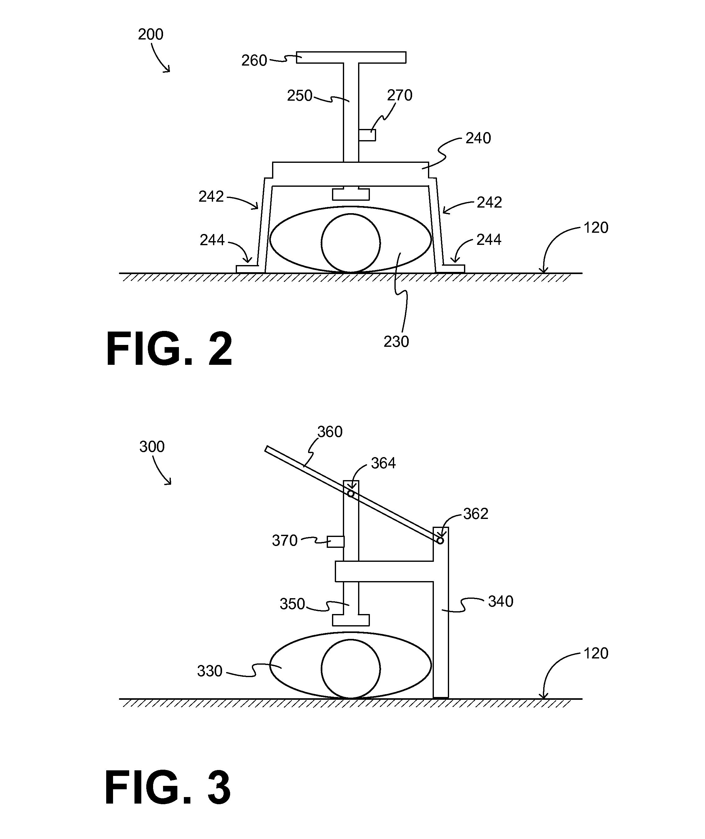
[0062]Embodiment 300 also includes an actuator 360 that is a handle. The handle can be moved up and down, to cause piston 350 to perform the up motions and the down motions. Handle 360 is movably coupled with piston 350 via a joint 364. Handle 360 rotates around a joint 362 in frame 340, and therefore operates as a lever for piston 350, providing mechanical advantage. Because of the mechanical advantage, handle 360 will have to be moved farther than handle 260, and with the same frequency, but with less force, in order to achieve the same profile of chest compressions.

[0063]In some of the embodiments, at least a portion of the base can be placed under the patient. An example is now described.

[0064]FIG. 4 is a diagram of a resuscitation scene. A rescuer 410 is performing chest compressions on a patient 430 by using a device 400, which is made according to embodiments.

[0065]Device 400 includes a frame 440 that has legs 442. In addition, a base is provided that has a portion 446 that i...


PUM


Abstract

In one embodiment, a manual CPR device, also known as a CPR derrick, includes a frame that is put close to a patient who is on the ground. The device also includes a piston that can be moved up and down, and is aligned to be over the patient's chest. The device also has an actuator that the rescuer can operate manually so as to move the piston up and down, which will deliver compressions to the patient's chest. A bottom stop prevents the compressions from being too deep. In some embodiments, proper dimensioning of the CPR derrick permits the rescuer to perform CPR chest compressions while standing up, i.e. without kneeling. The rescuer may be able to perform higher quality CPR, and for a longer time, giving more opportunity to a life-saving team to arrive in time.

Description

CROSS REFERENCE TO RELATED PATENT APPLICATIONS[0001]This patent application claims priority from U.S. Provisional Patent Application Ser. No. 61 / 711,633, filed on Oct. 9, 2012, titled: “Manual Device to Assist CPR Chest Compressions while Standing Up”, the disclosure of which is hereby incorporated by reference for all purposes.BACKGROUND[0002]Cardio-Pulmonary Resuscitation, also known as “CPR”, is often used to treat a patient whose heart has stopped beating. CPR includes delivering chest compressions and ventilations to the patient. CPR chest compressions are intended to cause the blood to continue circulating, so as to prevent damage to vital organs, such as the brain. Organizations such as the American Heart Association (AHA) have published guidelines about how the chest compressions should be performed, so as to be effective. The guidelines affect the compression depth, repetition rate, and so on.[0003]CPR may have to be performed for a long time, before competent help arrives....

Claims


Application Information

Patent Timeline
IPC IPC(8): A61H31/00
CPCA61H31/008A61H31/007A61H31/005A61H2201/0119A61H2201/1253A61H2201/1409A61H2201/1664A61H2201/501A61H2201/5064A61H2201/5097A61H2201/018
Inventor JOHNSON, BETHANY JOYCEDAYNES, JOHN CARLTONCHAPMAN, FRED W.MARX, JR., ROBERT P.KAVOUNAS, GREGORY T.VON SCHENCK, ERIK CARL BERNHARD
Owner PHYSIO CONTROL INC
Learn More