

Balancing a pendulum-absorber crankshaft
- Summary
- Abstract
- Description
- Claims
- Application Information
AI Technical Summary
Benefits of technology
Problems solved by technology
Method used
Image

Examples
Embodiment Construction
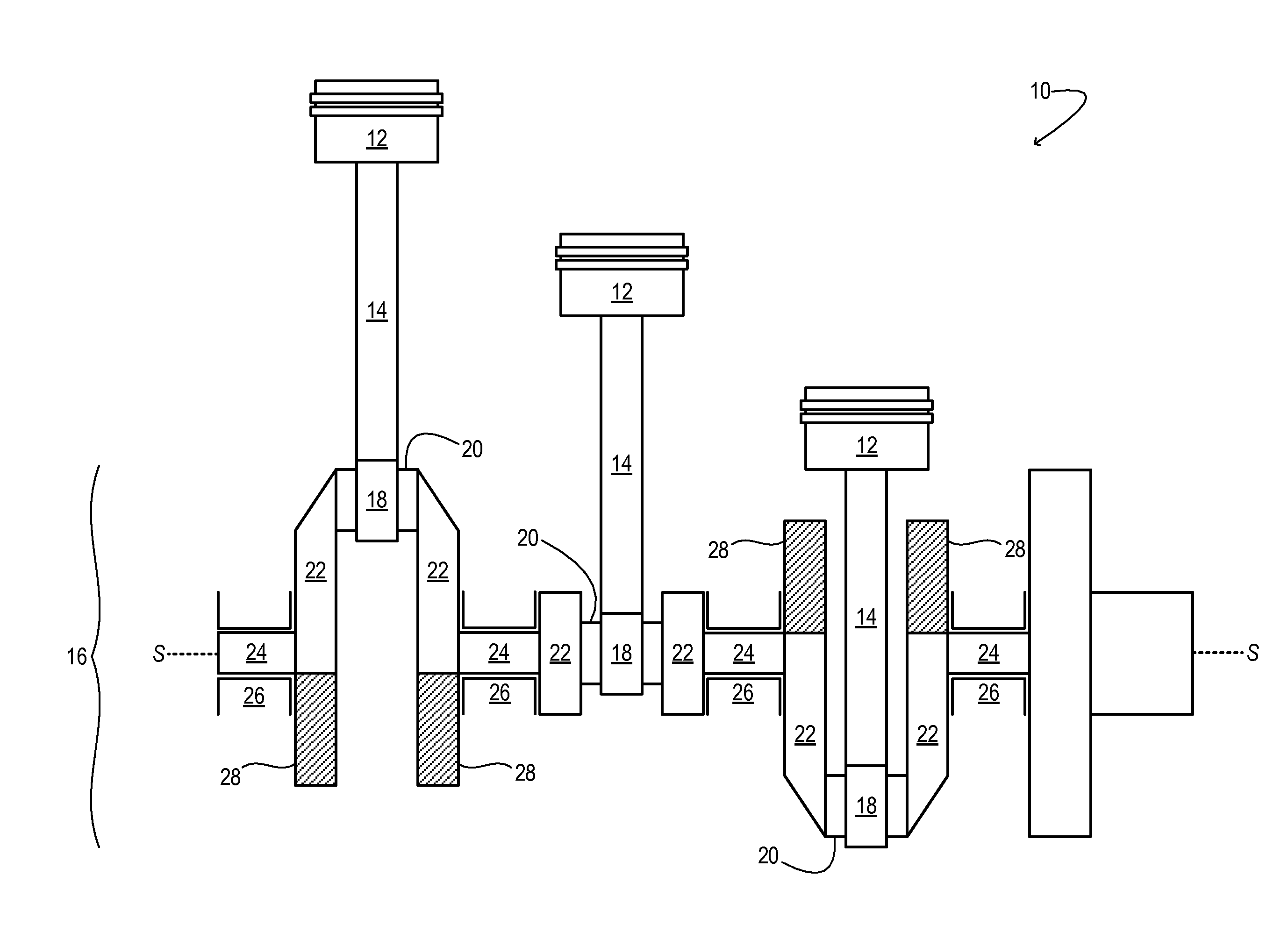
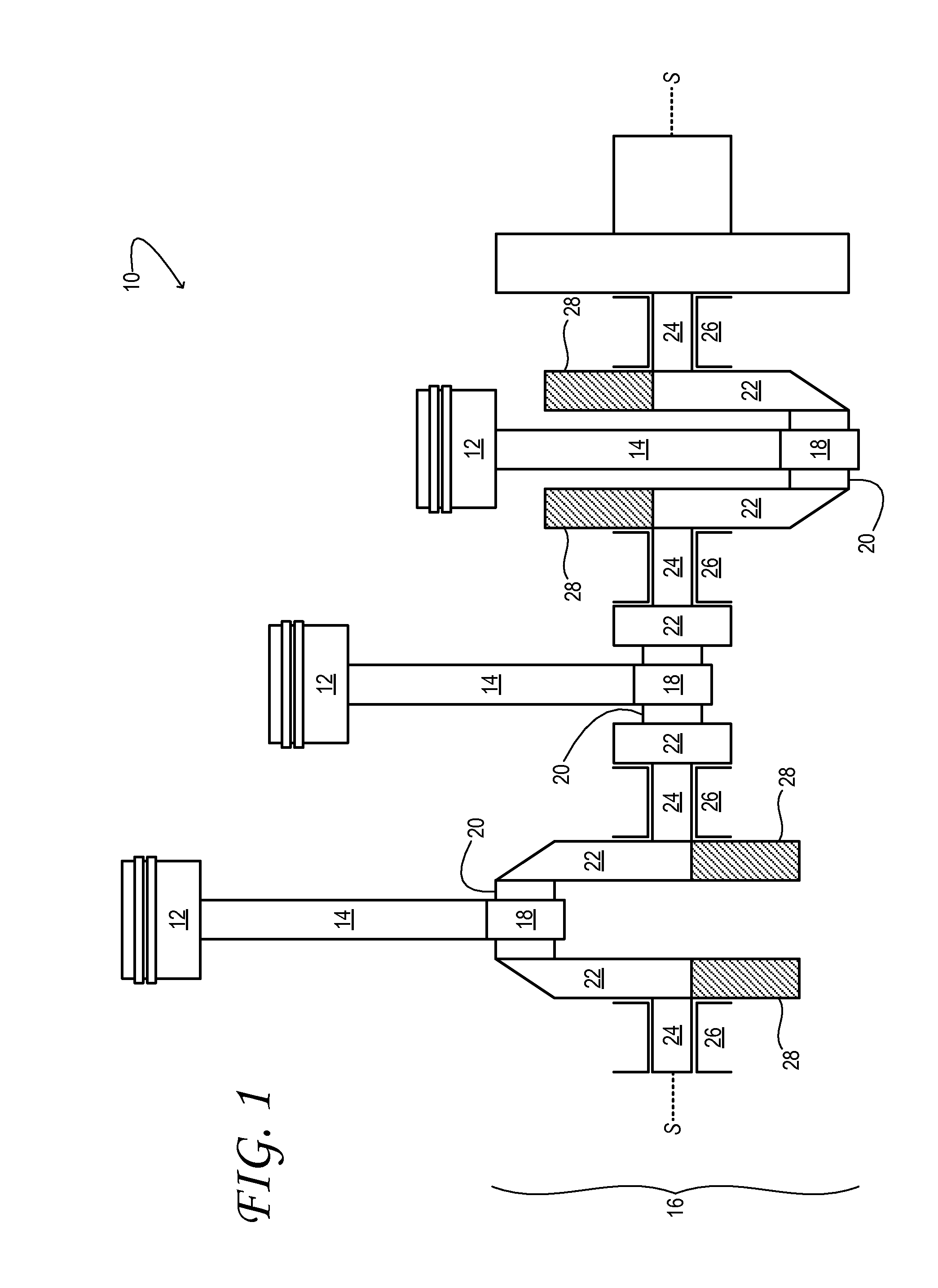
[0014]FIG. 1 schematically shows aspects of an example engine 10 of a motor vehicle. The engine includes a plurality of reciprocating pistons 12. Although three pistons are shown in FIG. 1, this disclosure is equally applicable to engines having more or fewer pistons. Each piston is pivotally coupled to one end of a corresponding piston rod 14. The other end of each piston rod is pivotally coupled to crankshaft 16 through a rod bearing 18. More specifically, a cylindrical crankpin journal—crankpin 20, hereinafter—is rotationally coupled inside each rod bearing. Each crankpin is located between a pair of cheeks 22, and coupled to the same. In the embodiment of FIG. 1, adjacent pairs of cheeks are connected by a plurality main journals 24. The main journals are rotationally coupled inside a corresponding plurality of main bearings 26.
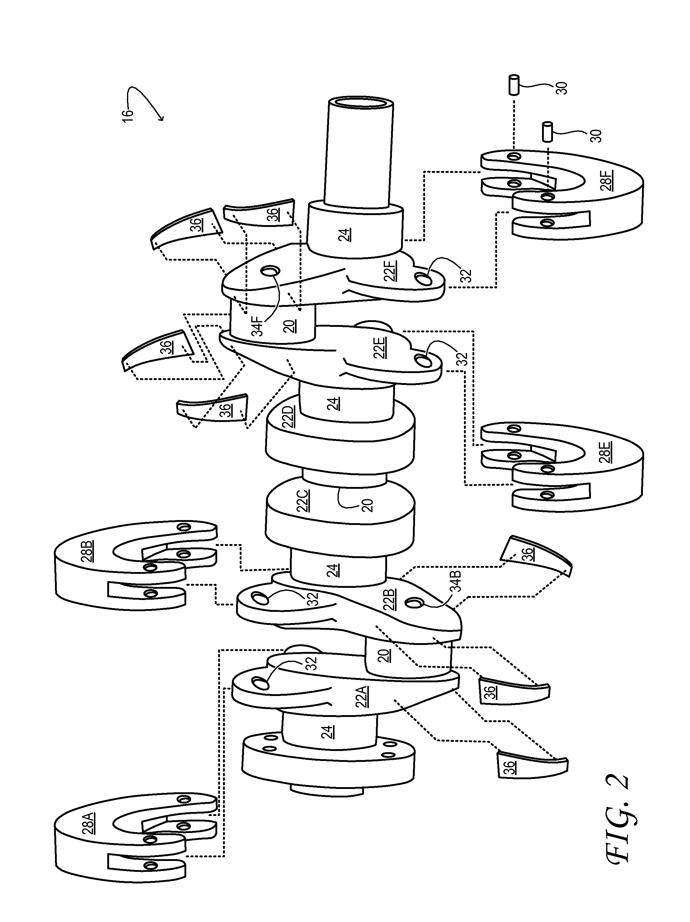
[0015]Crankshaft 16 includes a plurality of pendulum absorbers—pendula 28, hereinafter'which provide torsional-vibration absorption for the crankshaft. E...
PUM
| Property | Measurement | Unit |
|---|---|---|
| Length | aaaaa | aaaaa |
| Mass | aaaaa | aaaaa |
| Size | aaaaa | aaaaa |
Abstract
Description
Claims
Application Information