
Low Pressure Drop, Hight Efficiency Spark or Particulate Arresting Devices and Methods of Use

a technology of low pressure drop, which is applied in the field of low pressure drop, high efficiency spark or particulate arresting features and muffler features, can solve the problems of increasing energy consumption and achieves the effects of increasing energy consumption, increasing pressure drop, and reducing engine or machine performan

Active Publication Date: 2014-04-17
UNIVERSAL ACOUSTIC & EMISSION TECH
View PDF2 Cites 9 Cited by
  • Summary
  • Abstract
  • Description
  • Claims
  • Application Information

AI Technical Summary

Benefits of technology

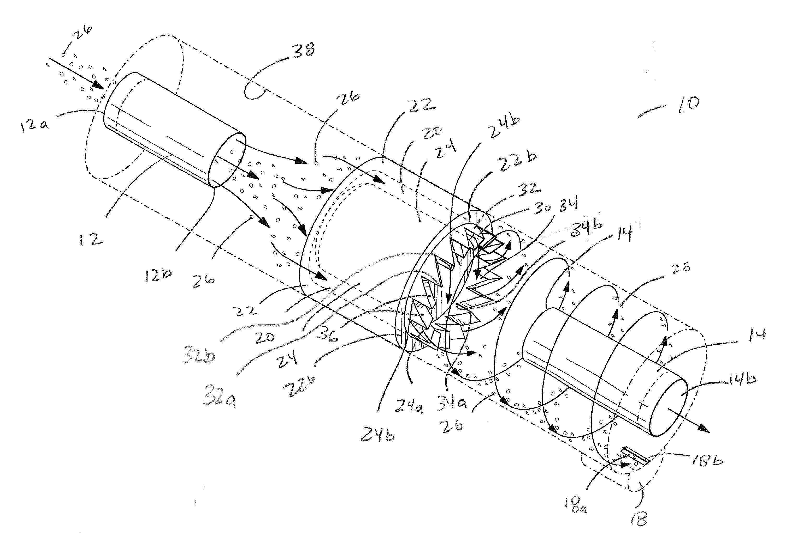
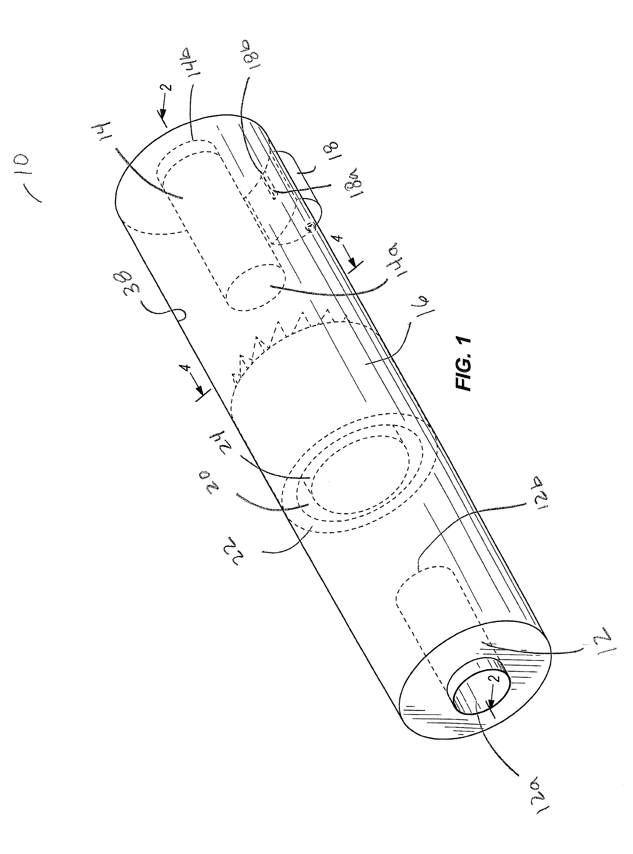
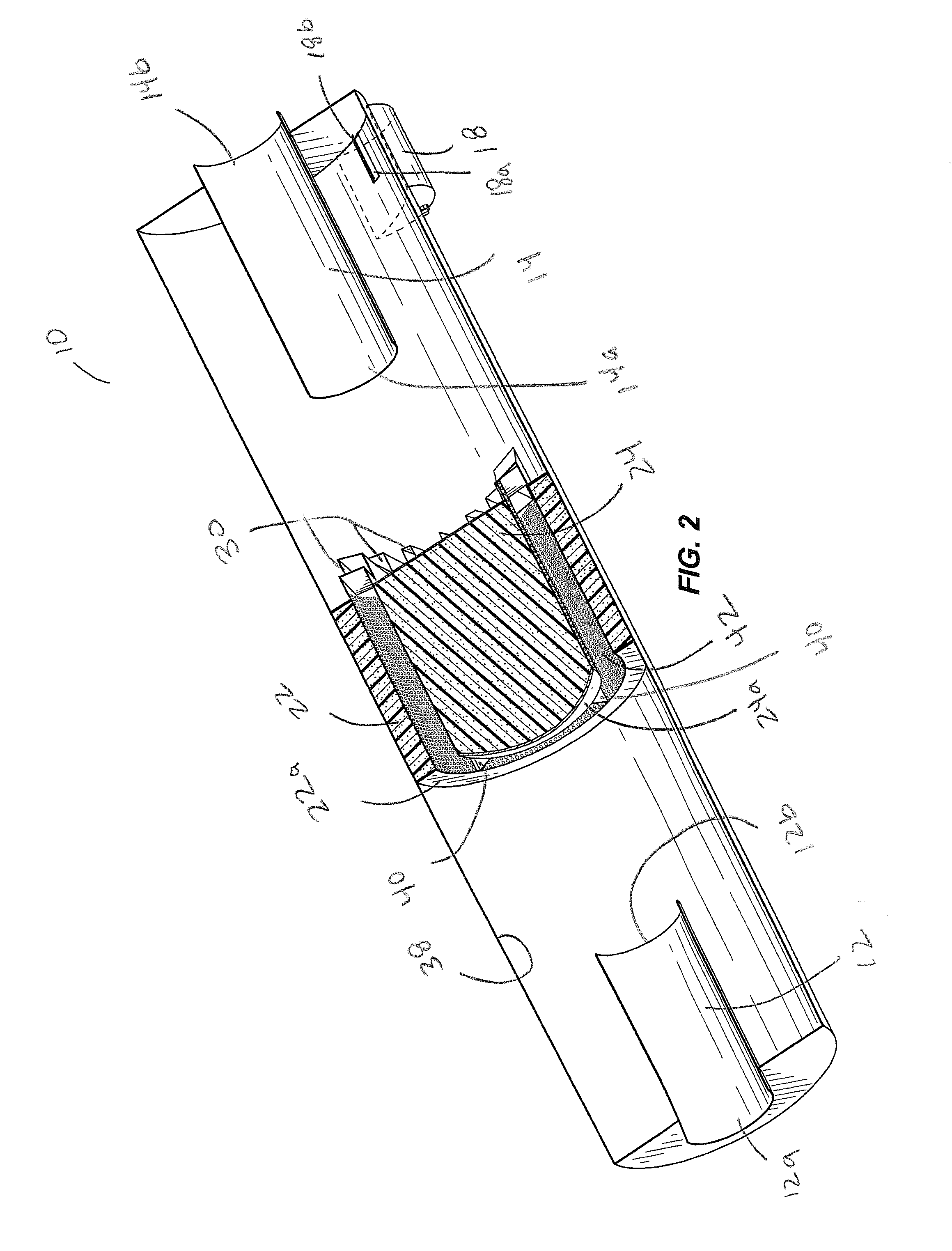
The patent text describes devices that can separate solid particulate matter from exhaust or gas flow in muffler systems. These devices have a cylindrical body with an annular channel that allows for centrifugal flow and the separation of particulate matter. The devices also have low pressure drop and high efficiency, making them desirable for use in mufflers. The text also describes the use of acoustic silencers that can reduce noise and the need for additional mufflers. The acoustic silencers have a unique design that allows for the separation of particulate matter and the creation of a spiral flow. The patent text also describes the use of perforated liners and radial spokes to support the structure of the devices. Overall, the patent text describes devices that can effectively separate particulate matter from exhaust or gas flow and reduce noise in mufflers.

Problems solved by technology

This piping typically results in an increased pressure drop, which consequently results in a decrease in engine or machine performance and an increase in energy consumption.

Method used


Image

  • Low Pressure Drop, Hight Efficiency Spark or Particulate Arresting Devices and Methods of Use
  • Low Pressure Drop, Hight Efficiency Spark or Particulate Arresting Devices and Methods of Use
  • Low Pressure Drop, Hight Efficiency Spark or Particulate Arresting Devices and Methods of Use

Examples


Embodiment Construction

[0017]Disclosed are devices having low pressure drop, high efficiency spark or particulate arresting features and muffler features. The disclosed devices further may he described by the following definitions and figures.

[0018]Unless otherwise noted, the terms used herein are to be understood according to conventional usage by those of ordinary skill in the relevant art. In addition to the definitions of terms provided below, it is to be understood that as used in the specification, embodiments, and in the claims, “a”, “an”, or “the” can mean one or more, depending upon the context in which it is used. For example. “an element” should be interpreted to mean “one or more elements,” depending upon the context in which it is used.

[0019]As used herein, “about”, “approximately,”“substantially,” and “significantly” will be understood by persons of ordinary skill in the art and will vary to some extent on the context in which they are used. If there are uses of the term which are not clear ...


PUM

PropertyMeasurementUnit
densityaaaaaaaaaa
surface areaaaaaaaaaaa
diameteraaaaaaaaaa

Abstract

Disclosed are devices that include spark or particle arresting, features and muffler features. The disclosed devices may include: (a) an upstream inlet receiving exhaust gas flow; (b) a downstream outlet discharging exhaust gas flow; (c) a cylindrical body disposed between the upstream inlet and downstream outlet; and (d) a particle trap having an opening for collecting particulate matter in the exhaust gas flow, the particle trap disposed downstream of the cylindrical body on a wall of the device. The cylindrical body of the devices typically includes an annular channel permitting axial flow of gas therethrough from an upstream end of the annular channel through a downstream end of the annular channel. The downstream end of the annular channel may be configured to have openings for discharging exhaust gas flow and imparting a spiral flow to the discharged gas flow. As gas exits the annular channel, the particulate matter is forced radially outward via centrifugal force towards the wall of the device where the particulate matter is collected in the particle trap.

Description

BACKGROUND AND SUMMARY[0001]The field of the invention relates to particulate arresting devices. In particular, the field of the invention relates to devices having low pressure drop, high efficiency spark or particulate arresting features and muffler features.[0002]Many muffler devices require a feature to separate solid particular matter from exhaust or gas flow. Such features sometimes are referred to as “spark arrestors” or “particle arrestors.” Spark or particle separation or entrapment typically has been accomplished by utilizing internal piping arrangements to generate a centrifugal flow in an exhaust stream that separates carbon particulate matter from the stream based on the higher density of the particulate matter relative to gas in the stream. This piping typically results in an increased pressure drop, which consequently results in a decrease in engine or machine performance and an increase in energy consumption. For these reasons, muffler devices having a high particula...

Claims


Application Information

Patent Timeline
Patent Type & Authority Applications(United States)
IPC IPC(8): B01D45/08
CPCF01N1/04F01N1/08F01N1/082F01N1/086F01N1/12F01N3/037F01N3/06F01N2230/02F01N2240/20Y02T10/12B01D45/08B01D45/12B01D45/16B01D46/2411F01M13/04
Inventor RAY, JR., ELDEN F.MORGAN, JEFFREY S.MAO, FUHE
Owner UNIVERSAL ACOUSTIC & EMISSION TECH
Learn More