Gas engine, control system and control method for gas engine

Active Publication Date: 2014-04-17
KAWASAKI HEAVY IND LTD
View PDF15 Cites 21 Cited by
  • Summary
  • Abstract
  • Description
  • Claims
  • Application Information

AI Technical Summary

Benefits of technology

[0017]In accordance with the present invention, it becomes possible to achieve advantages together that the knocking can

Problems solved by technology

This may lead to a situation in which a knocking is more likely to occur and NOx emissions in

Method used


Image

  • Gas engine, control system and control method for gas engine
  • Gas engine, control system and control method for gas engine
  • Gas engine, control system and control method for gas engine

Examples


Embodiment Construction

[0026]Hereinafter, an embodiment of the present invention will be described with reference to drawings. Throughout the drawings, the same or corresponding components are designated by the same reference symbols and will not be described in repetition.

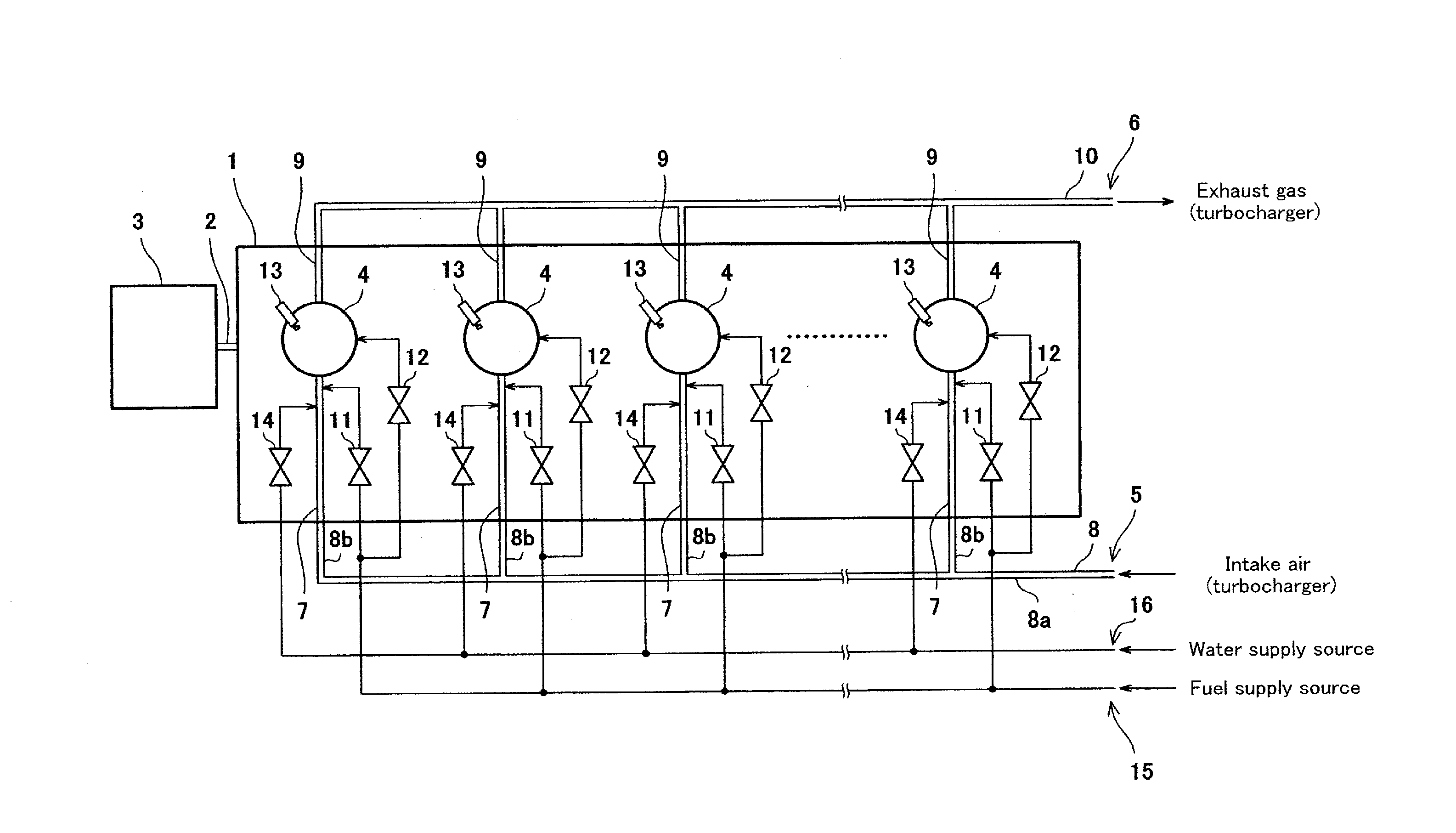
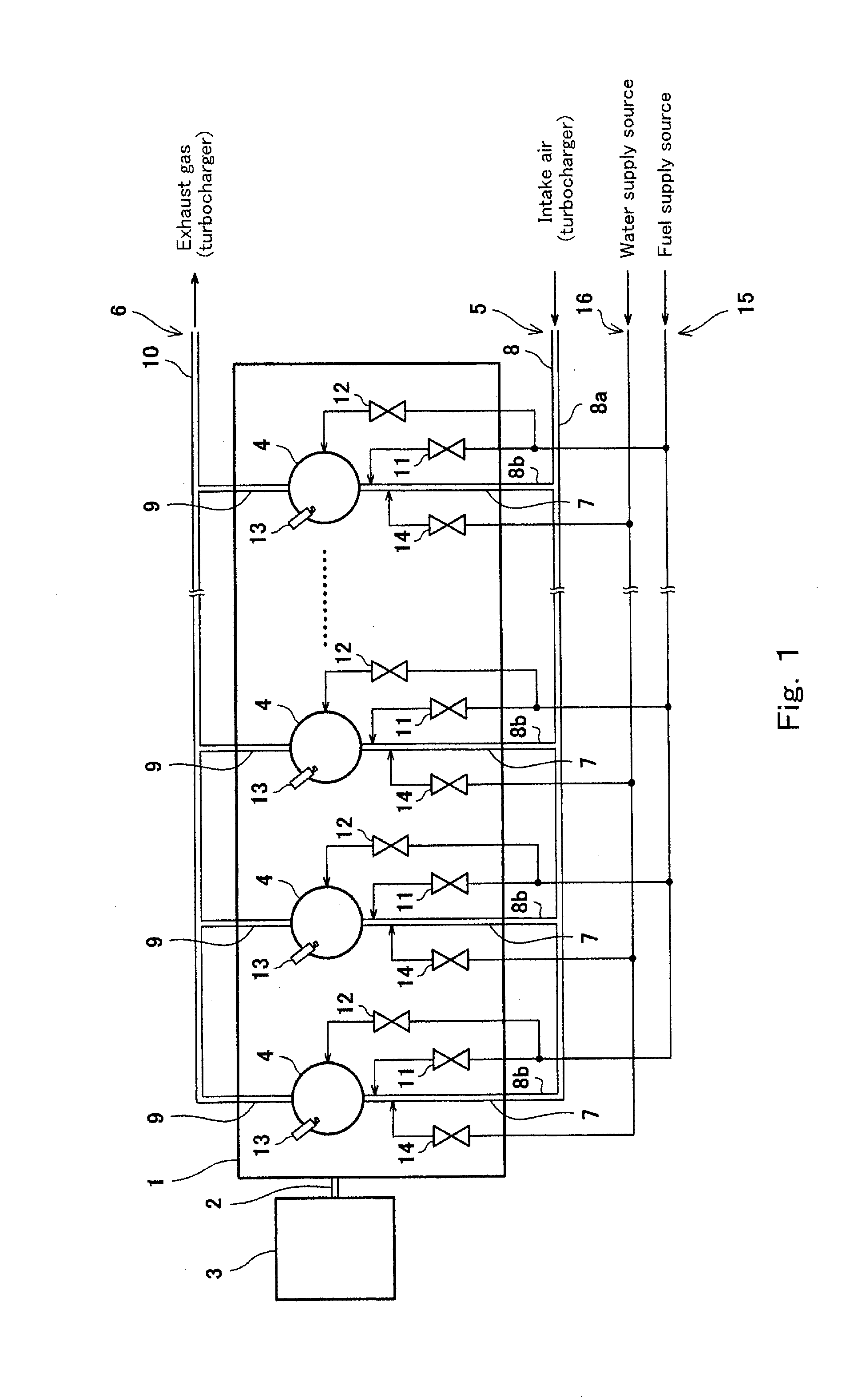
[0027]FIG. 1 is a conceptual view showing an overall construction of a gas engine 1 according to the embodiment of the present invention. As shown in FIG. 1, the gas engine 1 is configured to combust an air-fuel mixture which is a mixture of a gas fuel and intake air to generate a rotational output at an output shaft 2. The output shaft 2 is connected to, for example, an AC power generator 3. The output shaft 2 may be connected to a ship propulsive apparatus in place of the AC power generator 3. In this way, the gas engine 1 of the present embodiment is suitably used as the driving power source of the AC power generator 3 or the ship propulsive apparatus.

[0028]The gas engine 1 is a reciprocating four-stroke engine and includes a plurali...


PUM


Abstract

A control system in a gas engine includes a water injection means which injects water toward an interior of a cylinder in the gas engine; a water injection control means which controls the water injection section; and a knocking occurrence ratio measuring means which measures a measurement value of a knocking occurrence ratio in the cylinder. The water injection control means controls the water injection means to set the amount of the water injected toward the interior of the cylinder, based on a deviation between the measurement value and a target value.

Description

TECHNICAL FIELD[0001]The present invention relates to a control system and a control method for a gas engine which executes control for suppressing a knocking, and a gas engine including the control system.BACKGROUND ART[0002]In recent years, to achieve a high fuel efficiency and a high power generation efficiency, there has been proposed a power generation plant which employs a huge reciprocating gas engine as a driving source of a generator. As an ignition method of an air-fuel mixture in such a gas engine for power generation, there is known a spark ignition method which ignites the air-fuel mixture by a spark generated between electrodes of an ignition plug. In order to optimize the efficiency of the gas engine and further promote energy saving in the power generation plant, it is considered that it is necessary to activate the gas engine in a state in which an ignition timing is advanced up to MBT (minimum advance for best torque). However, as the ignition timing is advanced, a...

Claims


Application Information

Patent Timeline
IPC IPC(8): F02M25/03
CPCF02M25/03F02D35/027F02D41/0027F02D2200/0802F02M25/0227F02M21/0275F02M21/0284F02D19/024F02M25/028F02M21/0278G01L23/227F02D19/12Y02T10/12Y02T10/30
Inventor YOSHIHARA, SHINTARONAKAJIMA, YOUHEIIWASAKI, HIDEKAZUYOSHIMURA, KENJISAKAI, YOSHISHIGETOKUNAGA, YOSHIROU
Owner KAWASAKI HEAVY IND LTD
Why Eureka
Try Eureka