Wire harness

a wire harness and wire technology, applied in the direction of insulated conductors, power cables, cables, etc., can solve the problems of difficult to adopt the traditional noise filter, difficult to wind the thick wires around a small-diameter cylindrical member to a predetermined shape, etc., to achieve the effect of improving the conductance value and improving the structur

Active Publication Date: 2014-04-17
YAZAKI CORP
View PDF7 Cites 5 Cited by
  • Summary
  • Abstract
  • Description
  • Claims
  • Application Information

AI Technical Summary

Benefits of technology

[0025]According to the present invention, an effect is achieved which is that a high voltage wire harness, for which noise can be absorbed, and it is not necessary to secure a large space, can be provided.
[0026]In addition, according to the present invention, an effect is achieved which is that the inductance value can be increased.
[0027]According to the present invention, the following effect besides the above effects is also achieved. In other words, an effect is achieved which is that the wire harness itself can be bended and wired along a desired route.
[0028]According to the present invention, the following effect besides the above effects is also achieved. In other words, an effect is achieved which is that the wire harness can be provided with a protecting part.
[0029]According to the present invention, the following effect besides the above effects is also achieved. In other words, an effect is achieved which is that a better structure can be provided to the terminal which is connected to the end of the high voltage conduction path main body.

Problems solved by technology

However, it is difficult to adopt the traditional noise filter when thick wires are used.
The reason is that it is difficult to wind the thick wires around a small-diameter cylindrical member to a predetermined shape.
In addition, in view of the wiring space between the motor unit and the inverter unit, a larger space must be secured when the thick wires are used, and this is difficult.

Method used


Image

  • Wire harness
  • Wire harness
  • Wire harness

Examples


embodiment 1

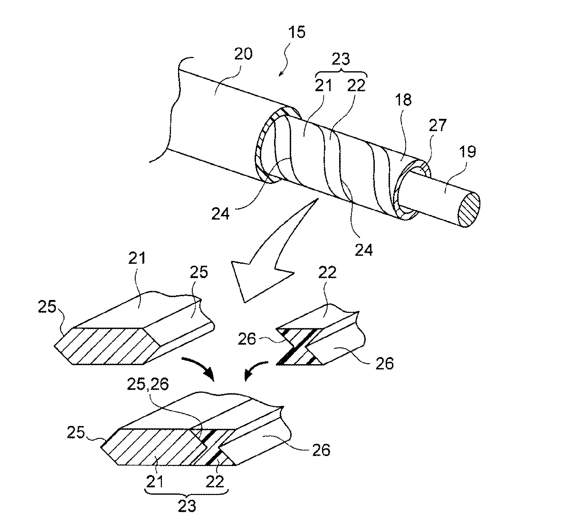
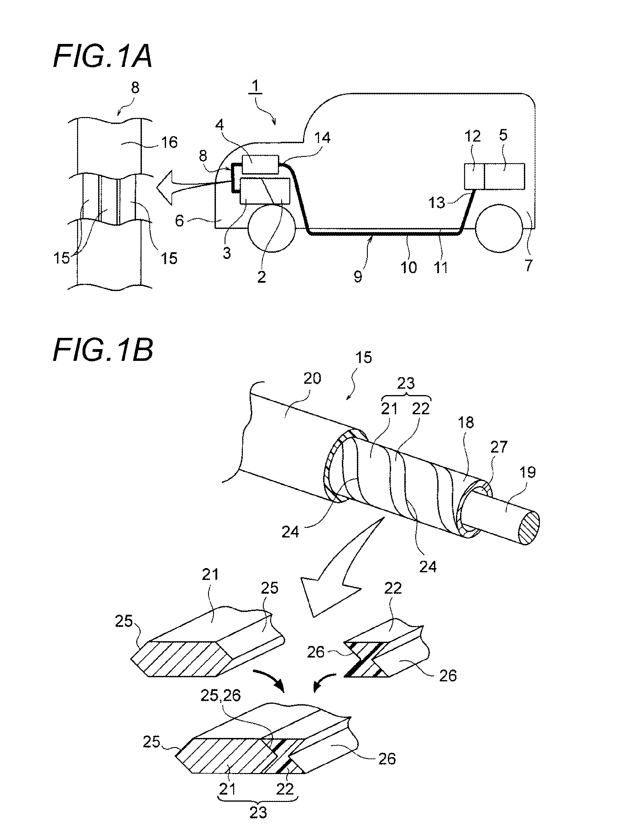
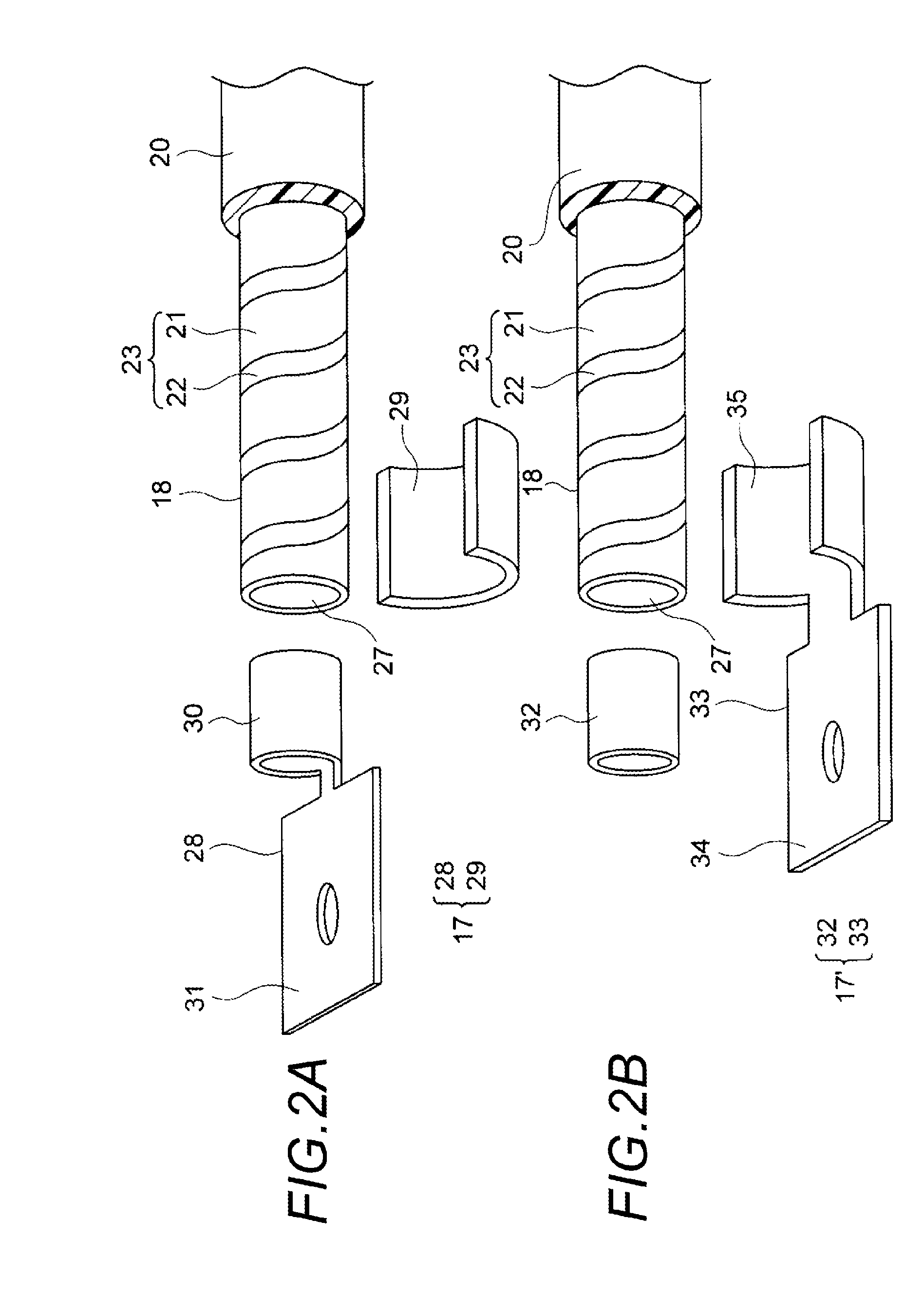
[0034]Next, an embodiment 1 is described with reference to the figures. FIGS. 1A and 1B are figures of the wire harness according to the present invention, in which FIG. 1A includes a schematic view which shows that wire harnesses are wired, and a construction figure of a wire harness, and FIG. 1B is a construction figure of a high voltage conduction path of FIG. 1A. FIGS. 2A and 2B are illustrative figures of configurations associated with terminal connection, in which FIG. 2A shows a construction in which an inner terminal is formed with an electrical contact part, and FIG. 2B shows a construction in which an outer terminal is formed with an electrical contact part.

[0035]In the embodiment, an example in which a wire harness of the present invention is applied to a hybrid vehicle (it may be an electric vehicle) is given and described.

[0036]In FIG. 1A, a reference number 1 indicates a hybrid vehicle. The hybrid vehicle 1 is a vehicle which is driven by mixing two powers of an engine...

embodiment 2

[0062]Next, an embodiment 2 is described with reference to the figures. FIGS. 3A and 3B are figures of another wire harness example according to the present invention, in which FIG. 3A is a schematic view which shows that the wire harnesses are wired, and FIG. 3B is a construction figure of a wire harness.

[0063]Furthermore, the components that are identical with those in the above-mentioned embodiment 1 are given identical numbers, and their detailed description is omitted.

[0064]In FIG. 3A, the wire harness 9 connects the battery 5 with the inverter unit 4, and the middle part 10 is wired under the vehicle body floor 11. The wire harness 9, like the wire harness 8 in the embodiment 1, also functions as a noise filter.

[0065]First, the composition and the structure of the wire harness 9 of the present invention are described.

[0066]Two wire harnesses 9 are wired side by side (only one is shown in the figure). The wire harness 9 includes a high voltage conduction path 15, an exterior me...


PUM

PropertyMeasurementUnit
voltage conductionaaaaaaaaaa
voltageaaaaaaaaaa
flexibilityaaaaaaaaaa

Abstract

A wire harness includes one or a plurality of high voltage conduction paths, each having a high voltage conduction path main body, and a terminal which is provided at an end of the high voltage conduction path main body. The high voltage conduction path main body is formed into a cylindrical shape by spirally winding a metal wire rod and an insulating wire rod, and side end surfaces, which face each other, of the metal wire rod and the insulating wire rod positioned to be adjacent to each other alternately, contact each other.

Description

CROSS REFERENCE TO RELATED APPLICATION[0001]This application is a continuation of PCT application No. PCT / JP2012 / 069514, which was filed on Jul. 31, 2012 based on Japanese Patent Application (No. 2011-167927) filed on Aug. 1, 2011, the contents of which are incorporated herein by reference. Also, all the references cited herein are incorporated as a whole.BACKGROUND[0002]1. Technical Field[0003]The present invention relates to a wire harness which includes one or a plurality of high voltage conduction paths.[0004]2. Background Art[0005]Various devices are loaded in a vehicle. The devices are provided with a lot of electrical components or electronic components. The devices are connected with one another by wire harnesses. It is known that the wire harness is provided with a noise filter as an EMC (Electro-Magnetic Compatibility) measure. A wire harness provided with a noise filter is disclosed in JP-A-2011-61610.[0006]A related noise filter disclosed in JP-A-2011-61610 is provided a...

Claims


Application Information

Patent Timeline
Patent Type & Authority Applications(United States)
IPC IPC(8): H01B9/02H01B7/00
CPCH01B7/0045H01B9/02B60R16/0207H01B9/006
Inventor TOYAMA, EIICHI
Owner YAZAKI CORP
Why Eureka
Try Eureka