Process for producing sound absorber and produced by the process, sound absorber and sound absorbing structure

a technology of sound absorber and process, which is applied in the direction of instruments, heat measurement, buttons, etc., can solve the problems that the above-mentioned conventional sound absorber or sound insulator cannot exhibit both sound absorbing properties and sound insulating properties, and the absorption of rigid materials is not expected to be rigid and not expected to exhibit sound insulating properties, etc., to achieve selective absorption of targeted specifics, improve productivity, and improve the effect of productivity

Inactive Publication Date: 2011-05-10
PRIME POLYMER CO LTD +1
View PDF30 Cites 6 Cited by
  • Summary
  • Abstract
  • Description
  • Claims
  • Application Information

AI Technical Summary

Benefits of technology

[0016]According to this process, it is possible to produce a sound absorber efficiently since the holes can be formed simultaneously with molding of the sound absorber. In addition, stable sound absorbing properties can be obtained since removal of chips is unnecessary.
[0042]According to the invention, it is possible to obtain a process of production of a sound absorber excellent in productivity and quality stability and capable of absorbing only a noise in a specific frequency band, a sound absorber, and a sound absorbing structure. Since holes communicating with the internal void layer can be formed simultaneously with the molding, post processing for perforation becomes unnecessary, whereby productivity is improved. Further, the shape or morphology of the hole (presence or non-presence of the skin layer on the inner peripheral surface of the hole, or the width of the skin layer and so on) can be suitably selected or combined, thereby enabling selective absorption of targeted specific and multiple frequency ranges. In addition, due to the presence of dense skin layers, it is possible to obtain a sound absorber exhibiting sound insulating properties.

Problems solved by technology

Such a sound absorber is not rigid and not expected to exhibit sound insulating properties.
Therefore, generally, such a sound insulator is not expected to exhibit sound absorbing properties.
The above-mentioned conventional sound absorber or sound insulator cannot exhibit both sound-absorbing properties and sound-insulating properties.
Therefore, in order to provide a member having both sound absorbing and insulating properties, a troublesome process such as laminating a sound absorber and a sound insulator is required, which makes an entire production complicated.
If an attempt is made to ensure both sound-absorbing and insulating properties by laminating a sound absorber and a sound insulator, any one of product properties, such as heat resistance, rigidity, light weight, and shape, may be deteriorated.
To avoid this, it is required to optimize a material constituting a sound absorber and a sound insulator which are to be laminated, which may result in a time-consuming work of material selection.
Therefore, these have such disadvantages that they cannot be used suitably in structural bodies due to insufficient strength and are not expected to exhibit sound insulating properties.
In addition, the above-mentioned sound absorber and molded article of resin particles also have a disadvantage that it cannot absorb a plurality of frequency bands selectively although they can absorb a single frequency band by controlling the particle size.
In this respect, this technique is not satisfactory in productivity.Patent Document 1: JP-A-H07-168577Patent Document 2: JP-A-H10-329220Patent Document 3: JP-A-2000-52371Patent Document 4: JP-A-2003-337588Patent Document 5: WO03 / 91987
If an attempt is made to absorb an engine sound using the conventional sound absorber, there is a problem that both an uncomfortable noise and a comfortable sound are absorbed since the conventional sound absorber cannot select an absorbable frequency band.
Accordingly, there is a demand for a sound absorber which effectively absorbs an uncomfortable noise and does not absorb a comfortable sound.

Method used


Image

  • Process for producing sound absorber and produced by the process, sound absorber and sound absorbing structure
  • Process for producing sound absorber and produced by the process, sound absorber and sound absorbing structure
  • Process for producing sound absorber and produced by the process, sound absorber and sound absorbing structure

Examples


first embodiment of

Production Process

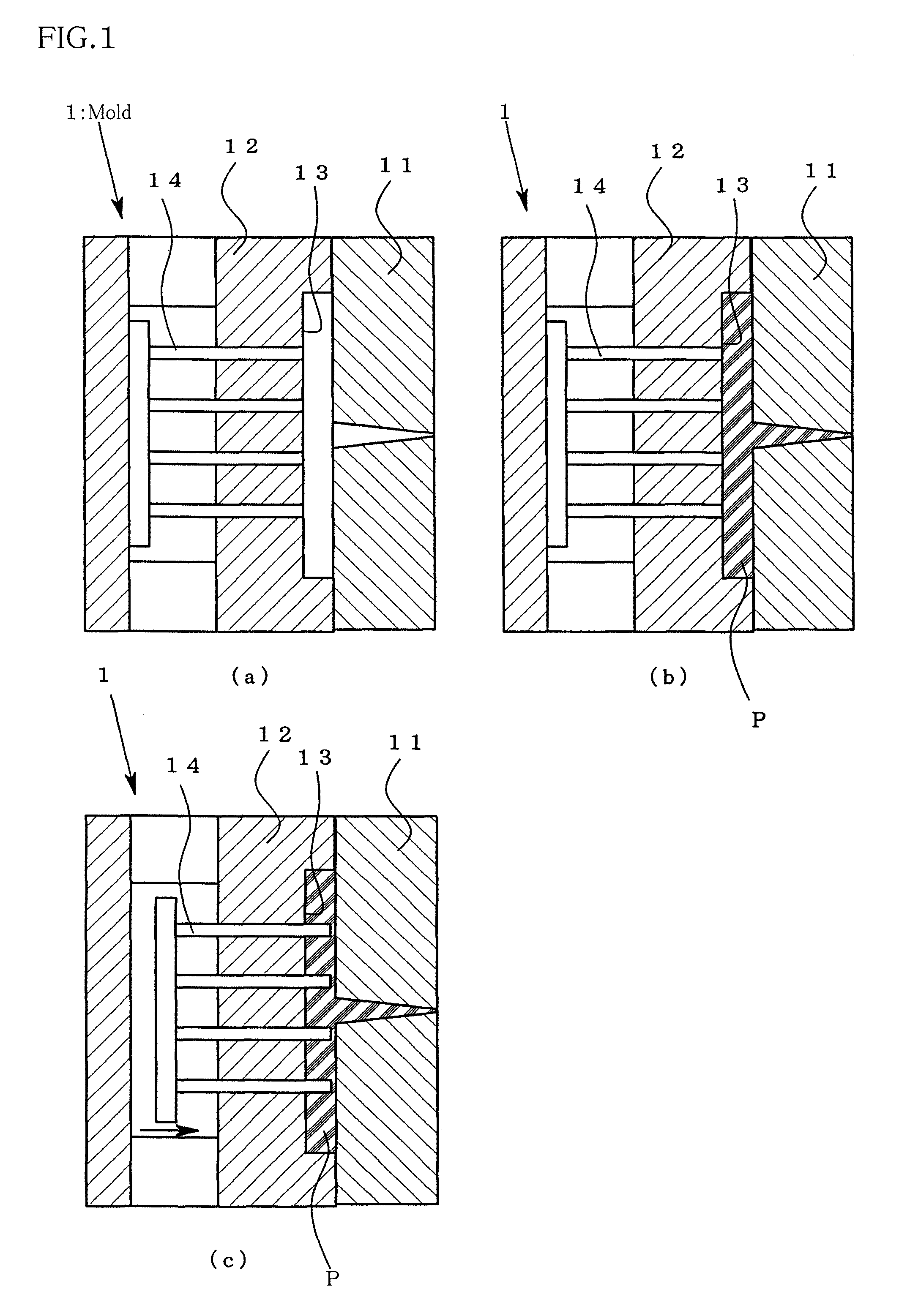
[0074]As shown in FIG. 1(a), the movable part 12 is moved toward the fixed part 1 to perform clamping.

[0075]After clamping, the resin material P is injected into the cavity 13, as shown in FIG. 1(b).

[0076]Subsequently, as shown in FIG. 1(c), the pin 14 is advanced immediately after injection to cause the pin 14 to project into the cavity 13.

[0077]The length of the projected part of the pin 14 may be a length which is enough to penetrate one of the skin layers and is not enough to reach the other skin layer. Preferably, the length of the projected part of the pin 14 is adjusted in advance such that the length becomes 30 to 90% of the thickness of a final molded article (sound absorber). Alternatively, changing the length of the projected part of the pin 14 may preferably be synchronized with retraction of the movable part 12.

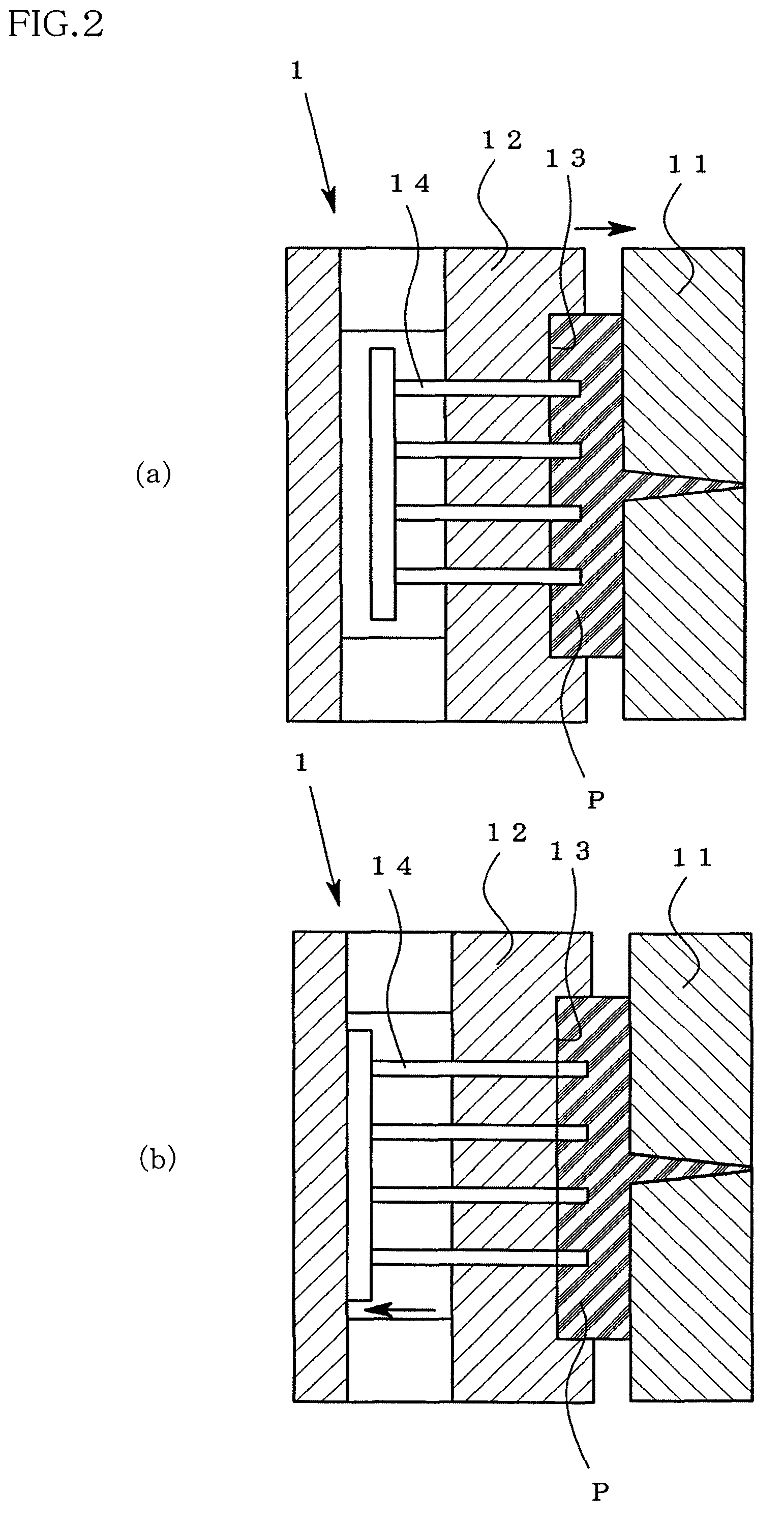
[0078]Subsequently, as shown in FIG. 2(a), the resin material P is caused to expand while opening the mold slightly. Preferably, the resin mate...

second embodiment of

Production Process

[0083]The procedures for molding a sound absorber in this embodiment are basically the same as the procedures for molding in the first embodiment as shown in FIGS. 1(a) to 1(c) and in FIGS. 2(a) and (b). In this embodiment, timing of retraction of the pin 14 shown in FIG. 2(b) is different from that in the first embodiment.

[0084]Specifically in this embodiment, the pin 14 is caused to retract when at least part of the inner peripheral surface of the hole of the resin material P which is in contact with the outer peripheral surface of the pin 14 is solidified to cause the skin layer to be formed.

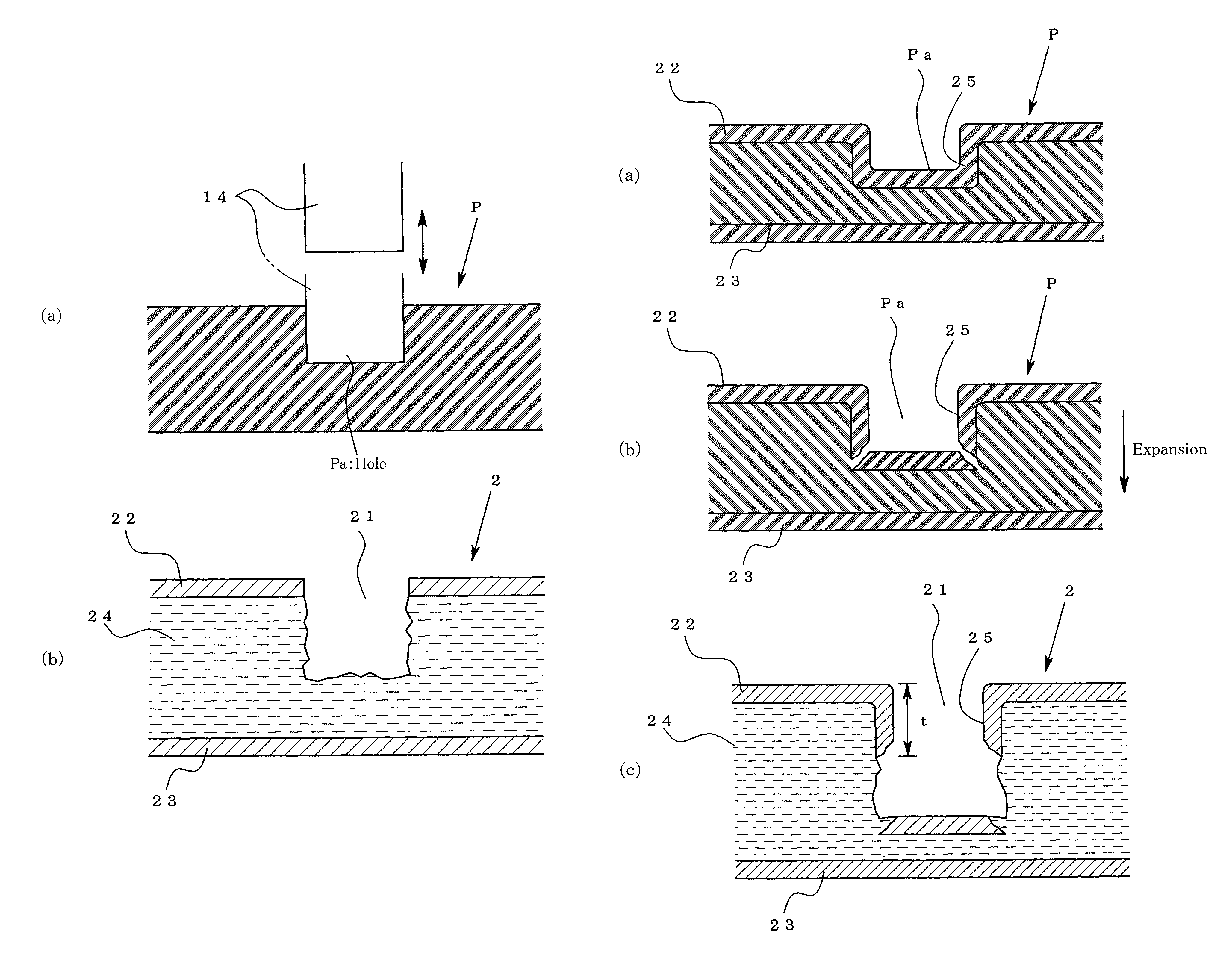
[0085]FIG. 4 is a schematic view showing the manner in which a sound absorber is formed in the second embodiment. FIG. 4(a) is an enlarged cross-sectional view of the hole of the resin material before expansion. FIG. 4(b) is an enlarged cross-sectional view of the hole part of the resin material immediately after the start of expansion. FIG. 4(c) is a cross-sectional view of...

third embodiment of

Production Process

[0089]The production process according to the third embodiment of the invention will be described below with reference to FIG. 5.

[0090]In this embodiment, after the resin material is injected into the cavity 13 after clamping as shown in FIG. 5(a), the movable part 12 is caused to retract to allow the resin material P to expand as shown in FIG. 5(b).

[0091]As shown in FIG. 5(c), before the resin material P in the cavity 13 is solidified, the pin 14 is advanced and caused to project into the cavity 13.

[0092]In this case, it is preferred that the projected part of the pin is long enough to penetrate one of the skin layers and is not long enough to reach the other skin layer. Preferably, the length of the projected part of the pin is 30 to 90% of the thickness of the final molded article (sound absorber).

[0093]The pin 14 is caused to retract with a prescribed timing as shown in FIG. 5(d).

[0094]The pin 14 is caused to retract, as explained in the first embodiment, befor...


PUM

PropertyMeasurementUnit
lengthaaaaaaaaaa
lengthaaaaaaaaaa
lengthaaaaaaaaaa

Abstract

A process for producing a sound absorber having skin layers constituting front and back surfaces and, interposed between the skin layers, a void layer having a plurality of pin formed holes, each hole having a depth which is enough to penetrate one of the skin layers and is not enough to reach the other skin layer. The sound absorber is formed of a resin material containing 2 to 60 wt % of reinforcing fibers with a length of 2 to 100 mm.

Description

TECHNICAL FIELD[0001]The invention relates to a process for producing a sound absorber having highly rigid skin layers constituting back and front surfaces and a void layer formed between the skin layers, and a sound absorber produced by the process and a sound absorbing structure.BACKGROUND[0002]Sound insulators and sound absorbers have heretofore been used to insulate noises. As the sound absorber, it is common to use a soft non-woven fabric or a molded foamed plastic article which absorbs an acoustic wave to a high degree. Such a sound absorber is not rigid and not expected to exhibit sound insulating properties. On the other hand, as the sound insulator, it is common to use a member having high density and high rigidity which hardly vibrates by an acoustic wave. To insulate noises, such a sound insulator insulates an acoustic noise by reflection, not by absorption. Therefore, generally, such a sound insulator is not expected to exhibit sound absorbing properties.[0003]The above-...

Claims


Application Information

Patent Timeline
Patent Type & Authority Patents(United States)
IPC IPC(8): E04B1/82B28B1/48E04B1/84B28B1/00E04B1/74B32B37/00
CPCB29C44/005B29C44/3415B29C44/583B29C45/2628G10K11/168B60R13/0815B60R13/0838G10K11/16B60R13/08B29C45/26B29C45/56G01K11/16
Inventor SAITO, YOSHIAKISUGAWARA, MINORUGODA, HIROFUMISUGA, TAKEHARUOKAMURA, MASAHARUSAKAI, TOSHIFUMI
Owner PRIME POLYMER CO LTD
Why Eureka
Try Eureka