Rotary Feed Dispensing Apparatus

a technology of feeding apparatus and rotary rod, which is applied in the direction of centrifugal wheel fertilisers, ways, roads, etc., can solve the problems of burning motors, and achieve the effect of convenient us

Active Publication Date: 2014-04-17
WISECARVER ROBERT TODD
View PDF3 Cites 9 Cited by
  • Summary
  • Abstract
  • Description
  • Claims
  • Application Information

AI Technical Summary

Benefits of technology

[0011]A further object of this invention is to provide a rotary feed dispensing apparatus, as aforesaid, that is easy is to use.

Problems solved by technology

More particularly, clumpy feed material may become lodged in a feed transmission channel and, as a result, feed is not even received into the impellors and is not ejected into the air.
Further, clumpy feed material already in an impellor assembly my cause the impellors to jam which, in turn, may cause the motor to burn up.

Method used


Image

  • Rotary Feed Dispensing Apparatus
  • Rotary Feed Dispensing Apparatus
  • Rotary Feed Dispensing Apparatus

Examples


Embodiment Construction

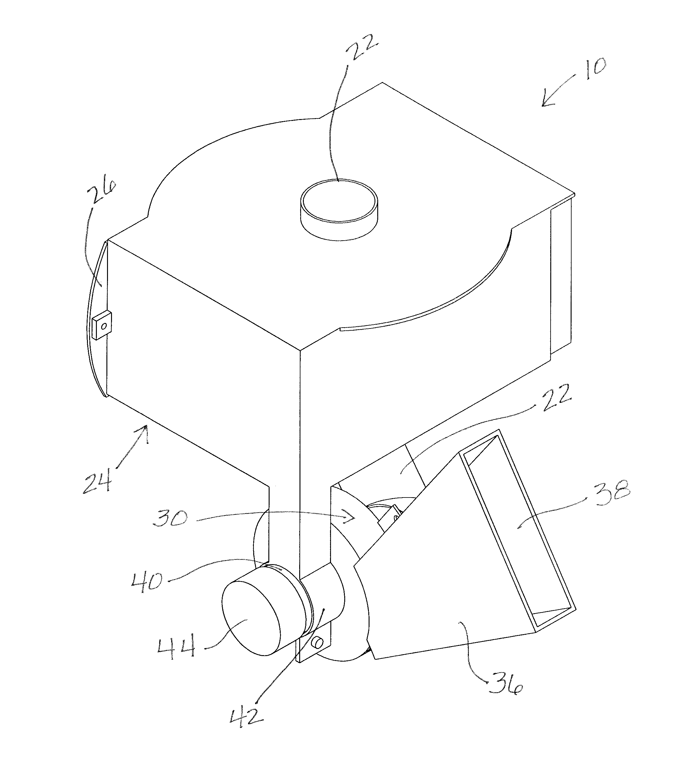
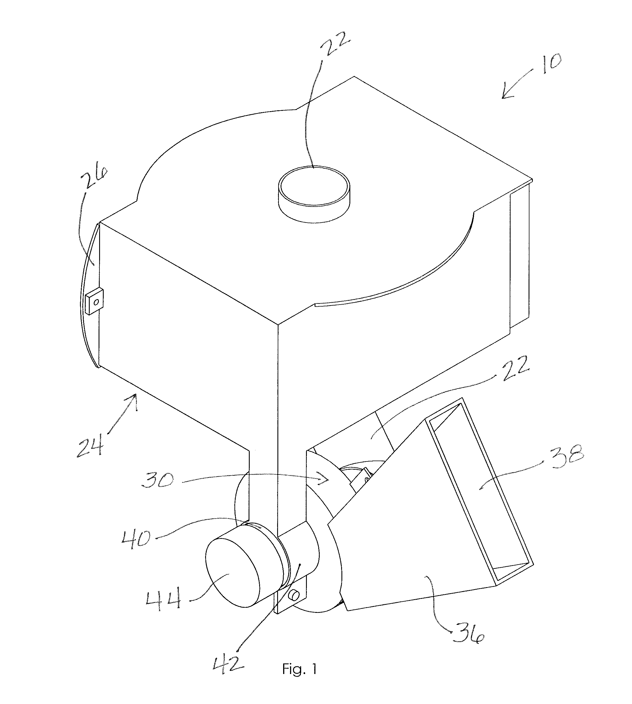
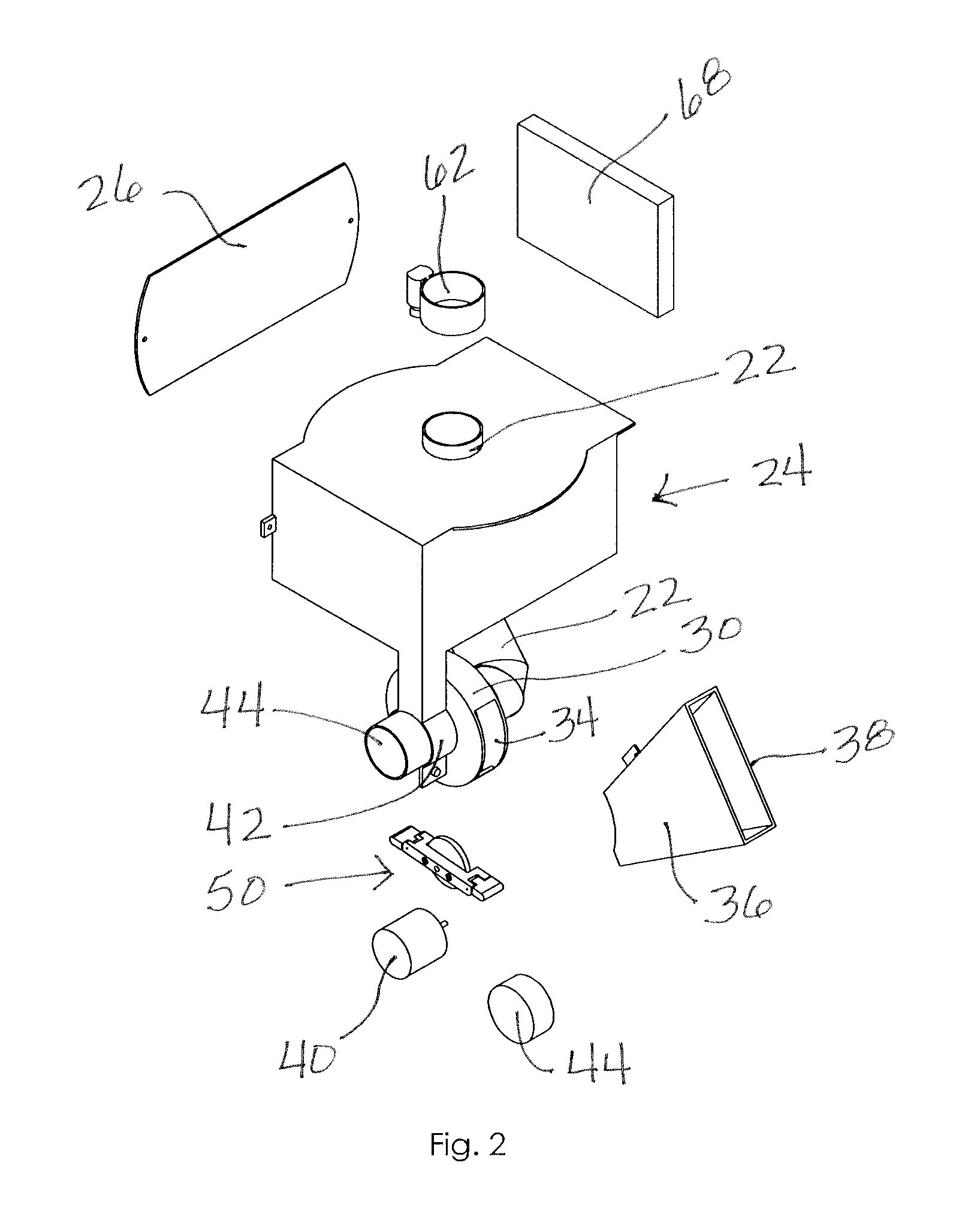
[0022]A rotary feed dispensing apparatus according to a preferred embodiment of the present invention will now be described with reference to FIGS. 1 to 7 of the accompanying drawings. The rotary feed dispensing apparatus 10 includes a reservoir 20, a rotary dispenser 30, an impellor assembly 50 situated in the rotary dispenser 30, a motor 40 configured to operate the impellor assembly 50 to eject feed into the air.

[0023]The reservoir 20 is configured to hold a quantity of feed, such as grain or other granular food product (FIG. 6). The reservoir 20 may be removed from the rest of the apparatus 10 as will be described more below, such as to refill it with feed. The reservoir 20 may have a cylindrical configuration although a square, rectangular, or spherical configuration would also work to hold and distribute feed to the rotary dispenser 30.

[0024]The rotary dispenser 30 is situated downstream from the reservoir 20 (FIG. 6) and operatively connected thereto. More particularly, the r...


PUM


Abstract

A rotary feed dispensing apparatus includes a reservoir configured to hold feed. The apparatus includes a rotary dispenser having an inlet operatively coupled to the reservoir and a rotary dispenser outlet, the rotary dispenser defining a rotary dispenser interior area configured to selectively receive the feed from the reservoir through the rotary housing inlet. An impellor assembly is rotatably mounted in the rotary dispenser, the impellor assembly having an impellor body portion and at least one impellor end portion pivotally coupled to the impellor body portion. The impellor end portion is movable between an extended configuration and a folded configuration. A motor is operatively coupled to the impellor assembly and configured to rotate the impellor assembly when energized. The impellor end portion is configured to eject the feed from the rotary dispenser through the outlet when the motor is energized and the impellor end portion is at the extended configuration.

Description

BACKGROUND OF THE INVENTION[0001]The present invention relates generally to animal feeding devices and, more particularly, to a rotary feed dispensing apparatus configured to selectively eject stored feed into the air so as to provide feed to animals.[0002]Livestock are often fed from feeding devices such as hay troughs, barrels that hold large quantities of grain or other feed, or even from feed dumped on the ground. Deer and other animals may be fed using centrifugal feeders that distribute feed by distributing it in a 360 degree area. In addition, rotary feeders use an impellor assembly to throw feed into the air in a more focused area.[0003]Although assumably effective for their intended purposes, rotary feeders sometimes jam when the feed material becomes damp and clumpy or includes foreign objects that are unable to be ejected by the impellors. More particularly, clumpy feed material may become lodged in a feed transmission channel and, as a result, feed is not even received i...

Claims


Application Information

Patent Timeline
Patent Type & Authority Applications(United States)
IPC IPC(8): B65G31/04H01L31/042
CPCA01K5/0225A01K5/0291
Inventor WISECARVER, ROBERT TODD
Owner WISECARVER ROBERT TODD
Why Eureka
Try Eureka