
Anti-rotation system for box and pin connection

a technology of box and pin connection and anti-rotation, which is applied in the direction of screw threaded joints, hose connections, screw threaded joints, etc., can solve the problem of interfering with the key rotation key, and achieve the effect of preventing the decoupling of threaded tubulars

Active Publication Date: 2014-04-17
VETCO GRAY
View PDF11 Cites 24 Cited by
  • Summary
  • Abstract
  • Description
  • Claims
  • Application Information

AI Technical Summary

Benefits of technology

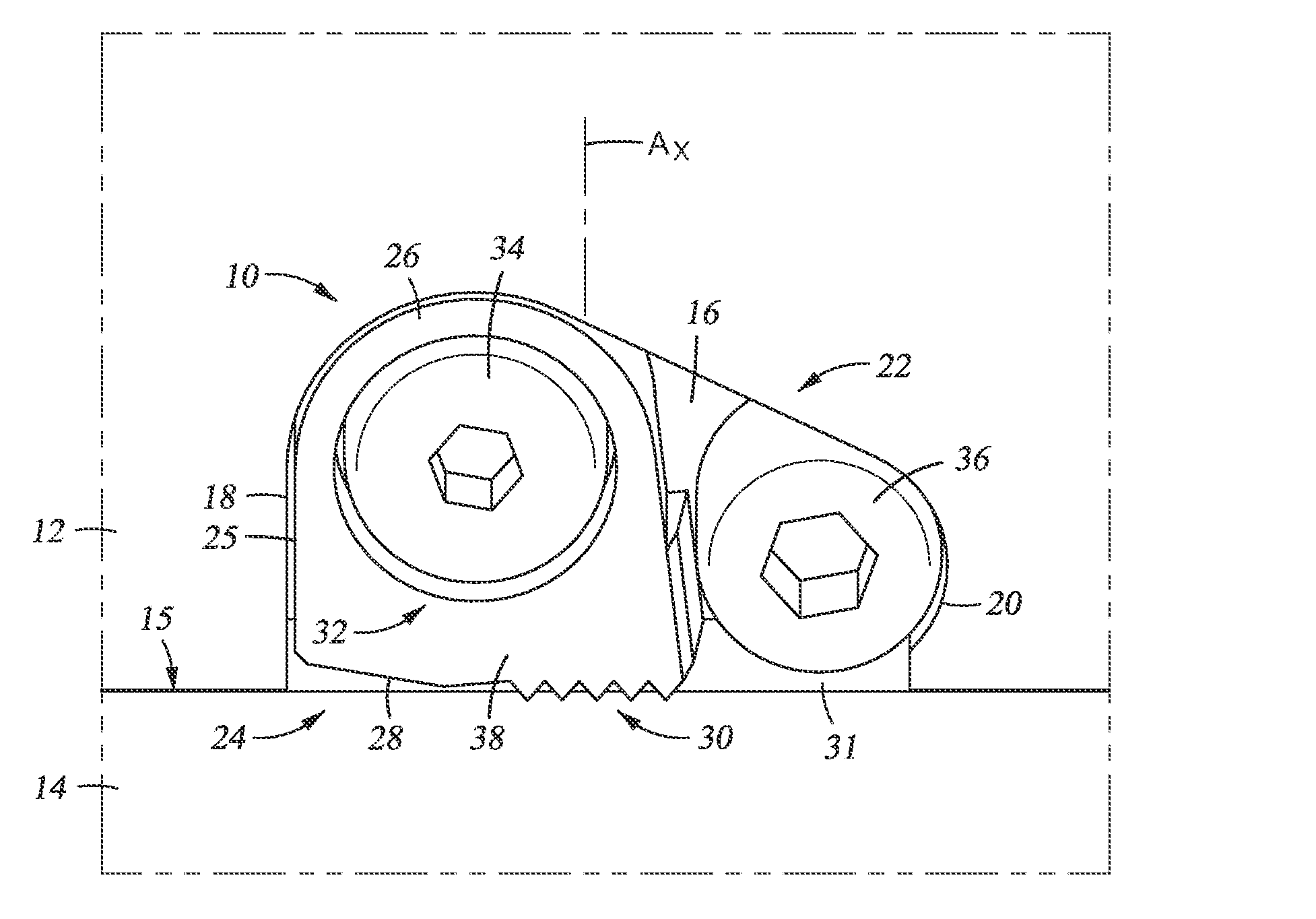
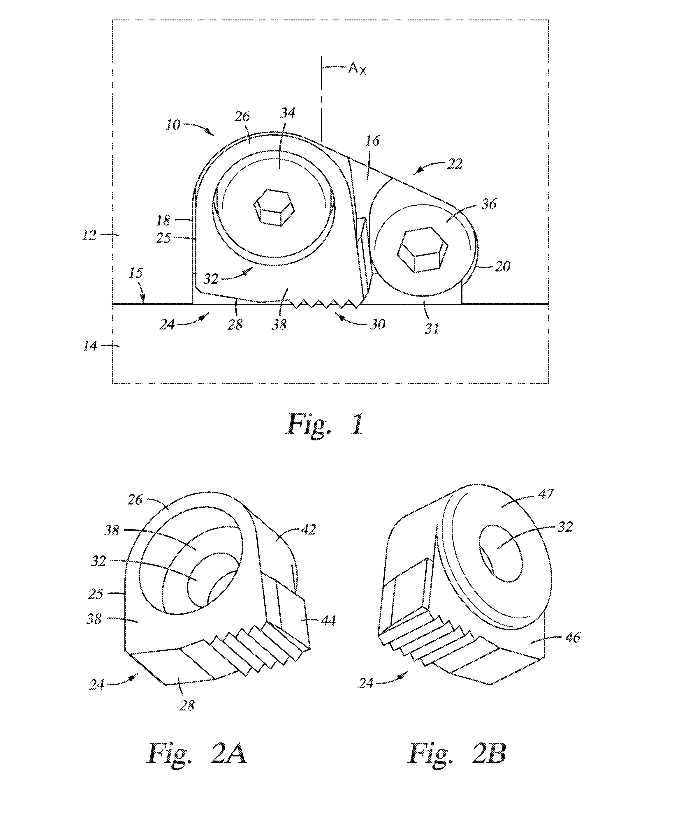
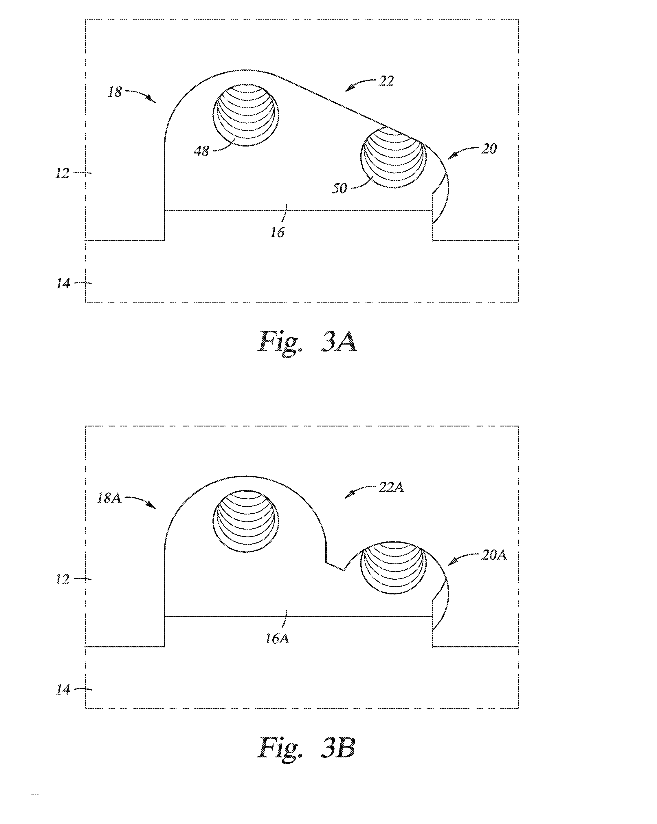
This patent pertains to an anti-rotation system for preventing two tubulars from becoming disconnected during use. The system includes a key with a varying radius that can be rotated into a locked position to prevent rotation. The key is pinioned in a recess formed on the outer surface of the first tubular using a fastener. The key has an outer edge that contacts a surface of the second tubular when rotated in a decoupling direction. This results in the generation of a force that opposes decoupling of the two tubulars. The patent also mentions the possibility of using a loading element to position the key. The technical effect of this patent is to provide a reliable and effective way to prevent accidental disconnection of tubulars during use, reducing the risk of damage or injury.

Problems solved by technology

Optionally, setting the key involves inserting a loading element in a slot that is tangentially formed on the first tubular, and which interferes with the key to rotate the key into contact with the radial surface.

Method used


Image

  • Anti-rotation system for box and pin connection
  • Anti-rotation system for box and pin connection
  • Anti-rotation system for box and pin connection

Examples


Embodiment Construction

[0034]The method and system of the present disclosure will now be described more fully hereinafter with reference to the accompanying drawings in which embodiments are shown. The method and system of the present disclosure may be in many different forms and should not be construed as limited to the illustrated embodiments set forth herein; rather, these embodiments are provided so that this disclosure will be thorough and complete, and will fully convey its scope to those skilled in the art. Like numbers refer to like elements throughout.

[0035]It is to be further understood that the scope of the present disclosure is not limited to the exact details of construction, operation, exact materials, or embodiments shown and described, as modifications and equivalents will be apparent to one skilled in the art, in the drawings and specification, there have been disclosed illustrative embodiments and, although specific terms are employed, they are used in a generic and descriptive sense onl...


PUM


Abstract

An anti-rotation system for use in retaining a threaded connection between a pin and a box. The anti-rotation system includes a key that sets in a recess formed in one of the box or pin. The key is selectively in contact with one of the other of the box or pin, and is activated when the threaded connection begins to decouple. The key is profiled and operates in a cam like fashion to wedge itself between the box and pin when these members begin to decouple and prevents further relative rotation.

Description

CROSS REFERENCE TO RELATED APPLICATIONS[0001]This application claims priority to and the benefit of co-pending U.S. Provisional Application Ser. No. 61 / 713,313, filed. Oct. 12, 2012, the hill disclosure of which is hereby incorporated by reference herein for all purposes.BACKGROUND OF THE INVENTION[0002]1. Field of the Invention[0003]This invention relates in general to production of oil and gas wells, and in particular to a system for maintaining a threaded connection between tubulars.[0004]2. Description of the Related Art[0005]Oil and gas wells typically include tubular strings that extend into the well in conjunction with drilling, casing, and production operations. The strings are made up as they are inserted into the well by using connectors to join discrete segments of pipe. Pipe connectors usually include a male portion having one end that connects to a pipe segment, and an opposite end with male threads, which is referred to as a pin. Connectors also include a female portio...

Claims


Application Information

Patent Timeline
Patent Type & Authority Applications(United States)
IPC IPC(8): F16L15/08
CPCF16L15/08E21B17/043F16B21/20F16B39/282F16B1/02
Inventor STEEN, THOMAS LOWELLPALLINI, JOSEPH WILLIAMBENSON, DANIEL CALEBFORD, DAVID LAWRENCEO'DELL, KEVIN EDWARDPETERS, STEPHEN DAVIDPATTERSON, JR., WILLIAM REY
Owner VETCO GRAY
Learn More