
Microcontroller-based multifunctional electronic switch

a multi-functional, electronic switch technology, applied in relays, pulse techniques, transportation and packaging, etc., can solve the problems of sparks igniting fire, mechanical switch is not suitable for installation, and is not suitable for working places

Active Publication Date: 2014-04-17
VAXCEL INT
View PDF5 Cites 22 Cited by
  • Summary
  • Abstract
  • Description
  • Claims
  • Application Information

AI Technical Summary

Benefits of technology

The present patent provides a multifunctional electronic switch that uses a microcontroller to perform at least two functions, including on / off switch control and dimming control. The switch detects external motion signals and converts them into a message carrying sensing signal, which is then read by the microcontroller. The microcontroller controls the conduction state or cut-off state of a controllable semiconductor switching element, which is connected between the load and a power source. The switch can control the conduction rate between the load and a DC power source or an AC power source. The contactless interface between the user and the switch creates a more user-friendly and efficient user experience.

Problems solved by technology

This mechanical-type switch is not suitable for installing in a space where has the concern of gas explosion, because an instantaneous surge current, produced by suddenly engaging or releasing the metallic contact of the switch, may generate electric sparks to ignite fire.
The operation of electronic switch with mechanical toggle means an inevitable contact by hand which is not appropriate in working places such as kitchens or hospitals.

Method used


Image

  • Microcontroller-based multifunctional electronic switch
  • Microcontroller-based multifunctional electronic switch
  • Microcontroller-based multifunctional electronic switch

Examples


Embodiment Construction

[0030]Reference will now be made in detail to the exemplary embodiments of the present disclosure, examples of which are illustrated in the accompanying drawings. Wherever possible, the same reference numbers are used in the drawings and the description to refer to the same or like parts.

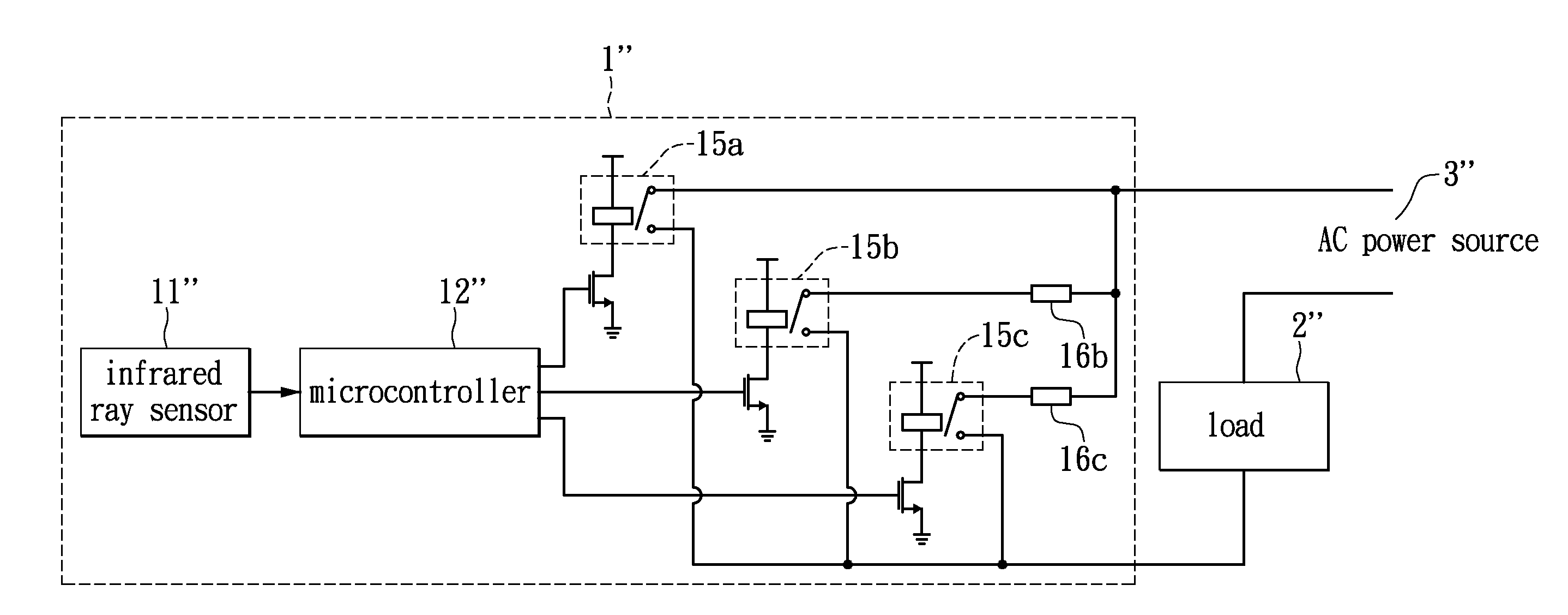
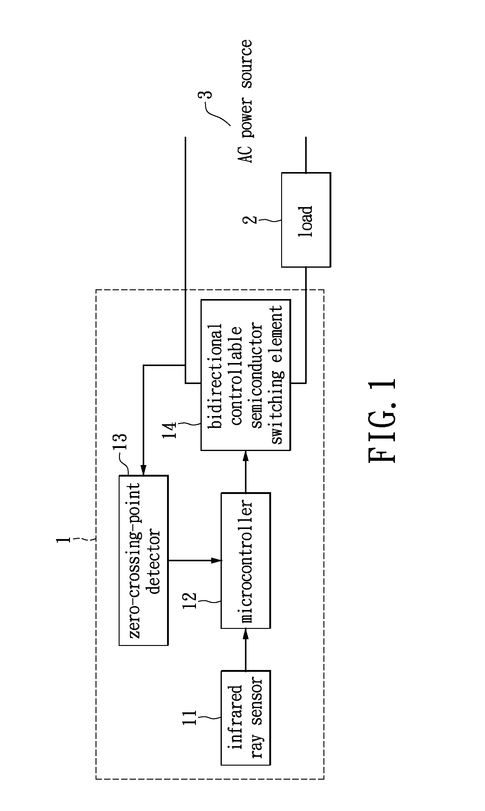
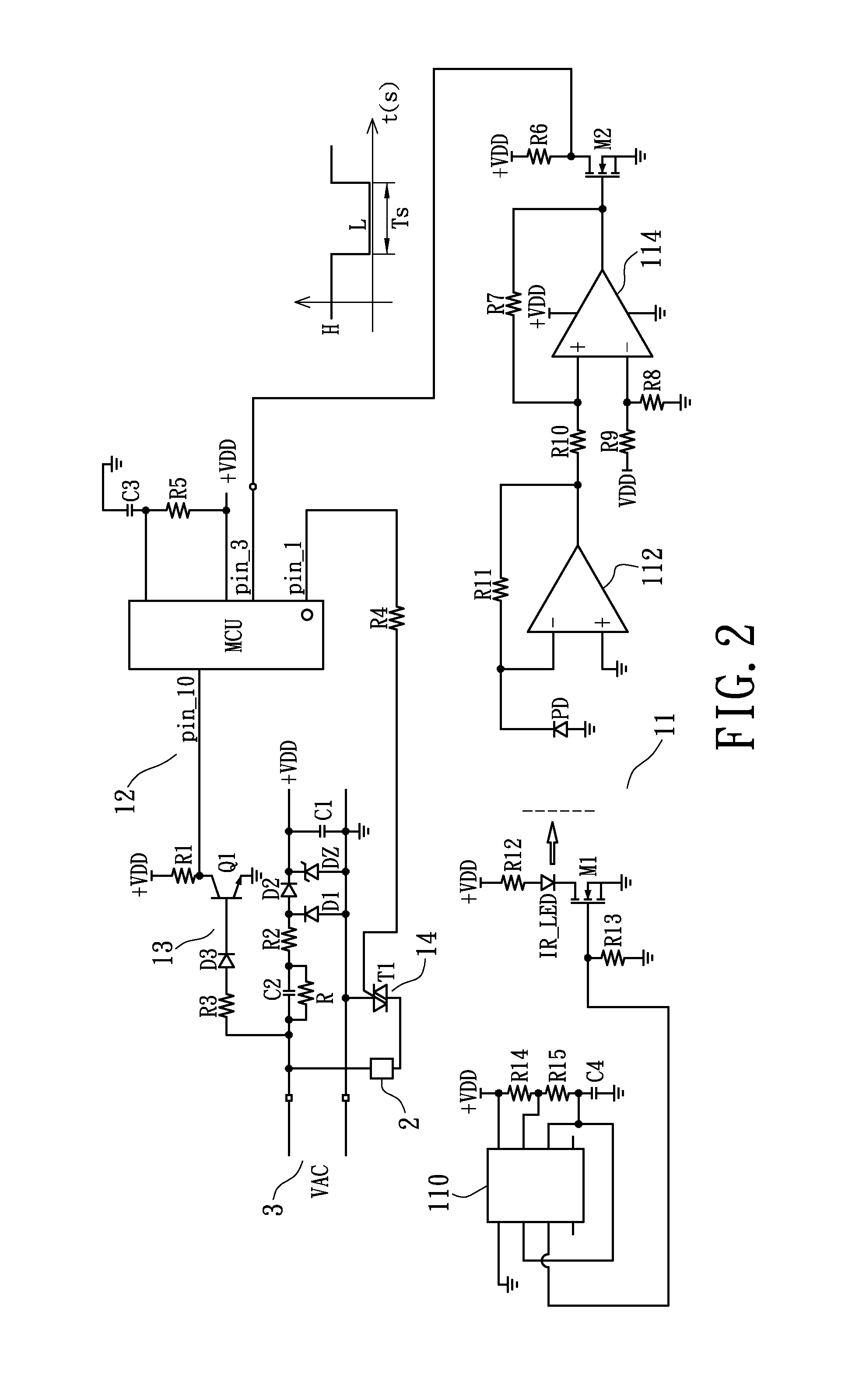
[0031]Referring to FIG. 1, FIG. 1 is a block diagram of a microcontroller based electronic switch using an infrared ray sensor as a detection means applied for an AC power source according to an exemplary embodiment of the present disclosure. A microcontroller based electronic switch 1 is connected in series to an AC power source 3, and is further connected to a load 2, so as to control AC power delivered to the load 2. The microcontroller based electronic switch 1 comprises at least an infrared ray sensor 11, a microcontroller 12, a zero-crossing-point detector 13, and a bi-directional controllable semiconductor switching element 14. The infrared ray sensor 11 is connected to one pin of microcontro...


PUM


Abstract

A microcontroller-based multifunctional electronic switch using a detection circuit design to convert external motion signals into message carrying sensing signals readable to the microcontroller. Based on the time length of sensing signals and the format of the sensing signals received in a preset instant period of time the microcontroller through the operation of its software program codes written in the OTPROM is able to recognize the working modes chosen by the external signal generating user and thereby selecting the appropriate loops of subroutine for execution. The system and method of the present invention may simultaneously be applicable to detection circuit design using infrared ray sensor, electrostatic induction sensor, conduction based touch sensor or push button sensor for performing multifunction such as controlling the on / off switch performance, the diming or speed control and the delay timer management within the capacity of a single lighting device or an electrical appliance.

Description

BACKGROUND[0001]1. Technical Field[0002]The present disclosure relates to a technology using a microcontroller with program codes designed to provide a user friendly solution for performing on / off switch control, diming control, and timer management for a lighting apparatus or an electrical appliance.[0003]2. Description of Related Art[0004]A mechanical-type electric switch is a manually operated electromechanical device. Its function is based on attaching or detaching two metal conductors to produce a short or open circuit, respectively. This mechanical-type switch is not suitable for installing in a space where has the concern of gas explosion, because an instantaneous surge current, produced by suddenly engaging or releasing the metallic contact of the switch, may generate electric sparks to ignite fire.[0005]A controllable semiconductor switching element, such as a triac, has nearly zero voltage between two output-electrodes in conduction mode and nearly zero current through two...

Claims


Application Information

Patent Timeline
IPC IPC(8): H03K17/56H03K17/78H05B37/02H05B44/00
CPCH03K17/56H03K17/78H05B37/0227H03K17/133H03K17/941H05B39/08H05B47/115H05B45/10Y02B20/40H05B47/16
Inventor CHEN, CHIA-TEH
Owner VAXCEL INT
Learn More