Filter for removing noise

Active Publication Date: 2014-04-17
SAMSUNG ELECTRO MECHANICS CO LTD
View PDF9 Cites 6 Cited by
  • Summary
  • Abstract
  • Description
  • Claims
  • Application Information

AI Technical Summary

Benefits of technology

The present invention is about a filter that can remove noise and improve performance by reducing impedance and improving insertion loss. It also aims to minimize the size of products while increasing performance and capacity and reduce manufacturing costs and improve productivity by simplifying structures and processes.

Problems solved by technology

When more data are communicated between a main device and a peripheral device over a GHz radio-frequency band, it is difficult to provide smooth data processing due to signal delay and other noises.
However, conventional EMI prevention parts are used only in limited regions such as specific portions and large-area substrates since they are coil-type and stack-type and have large chip part sizes and poor electrical characteristics.
However, in the conventional common-mode filter, as the frequency increases, the differential-mode impedance also increases, thus causing insertion loss.
Accordingly, characteristics of the common-mode filter are further deteriorated.
Further, in the conventional common-mode filter, the second magnetic substrate 3 is bonded to the insulating layer 2 by the adhesive layer 4, a magnetic flux flow is further disrupted by non-magnetic characteristics of the adhesive layer 4, thus causing rapid deterioration of characteristics.
In order to overcome the above problem, although it is possible to increase the length of the first coil pattern 2a and the second coil pattern 2b, in such a case, there are disadvantages such as an increase in manufacturing costs of the filter for removing noise and an increase in size of the filter for removing noise.

Method used


Image

  • Filter for removing noise
  • Filter for removing noise
  • Filter for removing noise

Examples


Embodiment Construction

[0062]Preferred embodiments of the present invention to achieve the above-described objects will be described with reference to the accompanying drawings. In describing the present embodiment, the same elements are represented by the same reference numerals, and additional description will be omitted below.

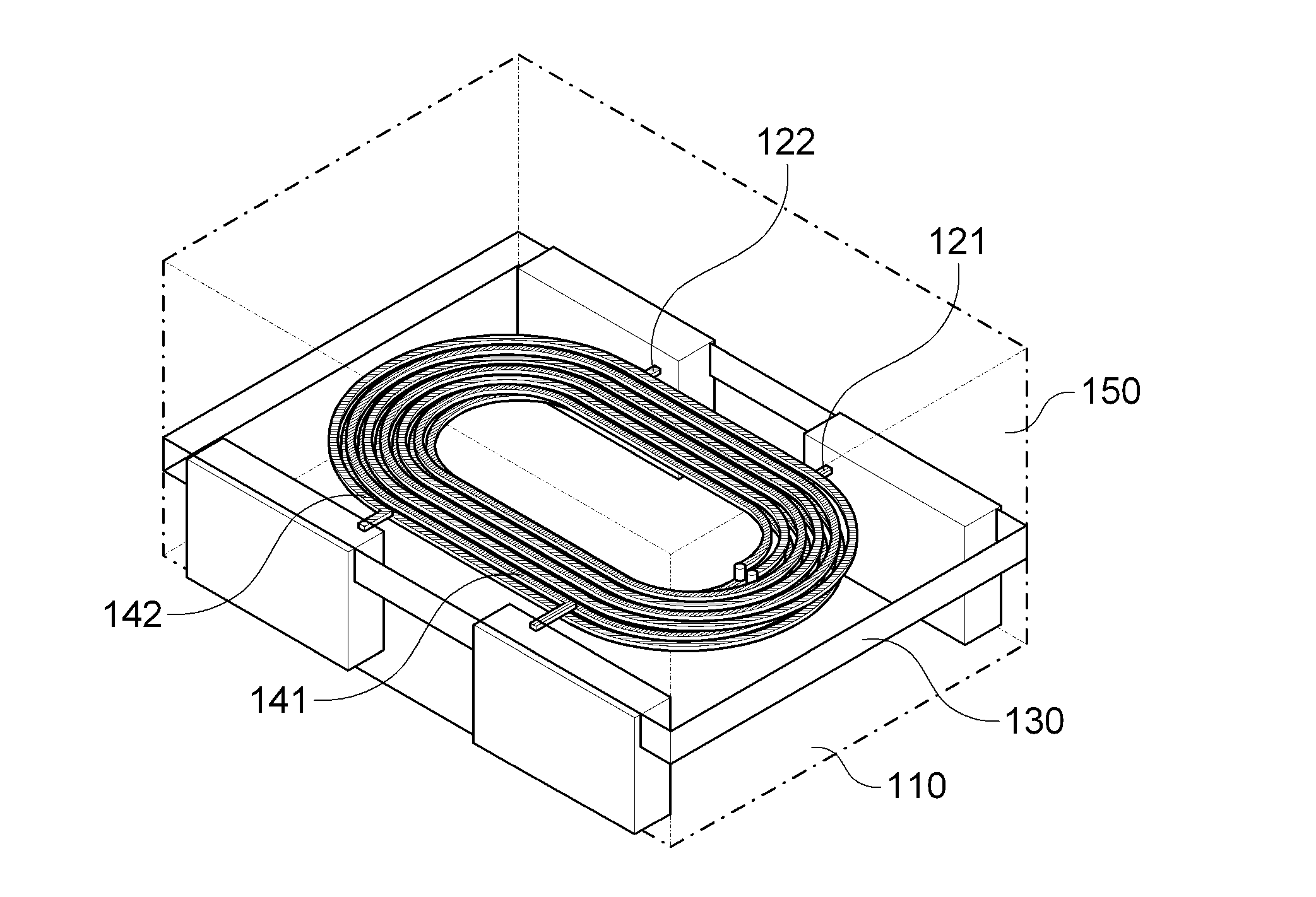
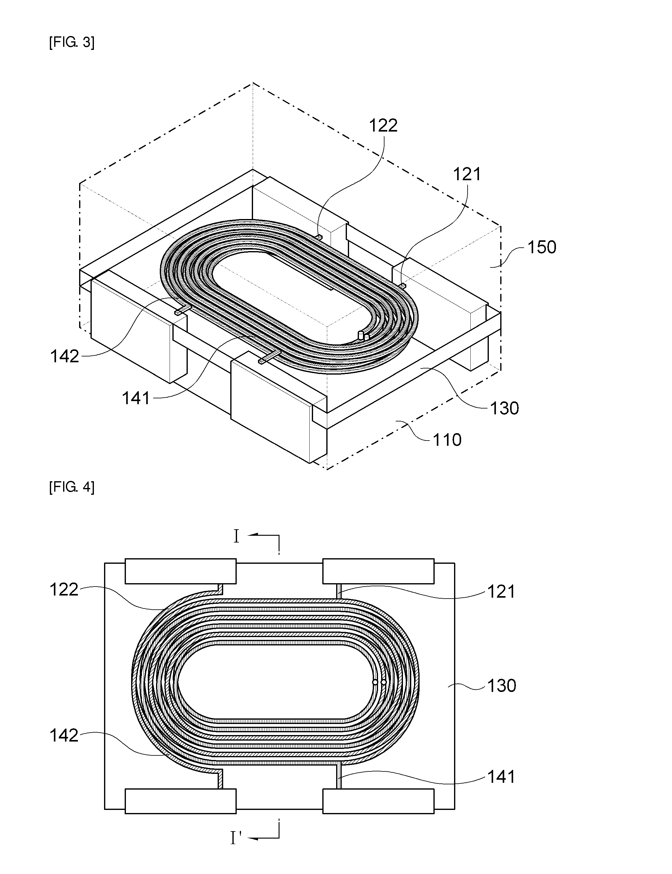
[0063]Hereinafter, an embodiment of a filter for removing noise in accordance with the present invention will be described in detail with reference to FIGS. 3 to 12.

[0064]FIG. 3 is a perspective view schematically showing an embodiment of a filter for removing noise in accordance with the present invention, FIG. 4 is a transverse cross-sectional view of FIG. 3, FIG. 5 is a cross-sectional view taken along line I-I′ of FIG. 4, FIG. 6a is a plan view schematically showing primary and secondary lower patterns of FIG. 3, FIG. 6b is a plan view schematically showing primary and secondary upper patterns of FIG. 3, FIG. 7 is a configuration diagram schematically showing magnetic fluxes d...


PUM


Abstract

The present invention discloses a filter for removing noise, which includes: a lower magnetic body; primary and secondary patterns spirally provided on the lower magnetic body in parallel to each other; an insulating layer for covering the primary and secondary patterns; and an upper magnetic body provided on the insulating layer, wherein the primary and secondary patterns are formed to have a ratio of vertical thickness (T) to horizontal width (W) of 0.27≦T / W≦2.4. According to the present invention, it is possible to improve performance and capacity by implementing high common-mode impedance in the same frequency and reduce manufacturing costs by simplifying structures and processes.

Description

CROSS-REFERENCE TO RELATED APPLICATIONS[0001]Claim and incorporate by reference domestic priority application and foreign priority application as follows:“CROSS REFERENCE TO RELATED APPLICATION[0002]This application claims the benefit under 35 U.S.C. Section 119 of Korean Patent Application Serial No. 10-2012-0086756, entitled filed Aug. 8, 2012, which is hereby incorporated by reference in its entirety into this application.”BACKGROUND OF THE INVENTION[0003]1. Field of the Invention[0004]The present invention relates to a filter for removing noise, and more particularly, to a filter for removing noise that can improve performance and capacity by implementing high common-mode impedance in the same frequency and improving insertion loss and reduce manufacturing costs and improve productivity by simplifying structures and processes.[0005]2. Description of the Related Art[0006]Electronic products, such as digital TVs, smart phones, and notebook computers, have functions for data commun...

Claims


Application Information

Patent Timeline
IPC IPC(8): H01F27/28
CPCH01F27/2804H01F27/006H01F2027/2809
Inventor AHN, YOUNG GHYUWI, SUNG KWONPARK, DONG SEOKKIM, YONG SUKPARK, ILL KYOOYOO, YOUNG SEUCKPARK, SANG SOO
Owner SAMSUNG ELECTRO MECHANICS CO LTD
Why Eureka
Try Eureka