System and method having an improved beam and beam coupling system

Active Publication Date: 2019-12-26
TEFFENHART JR THOMAS JOSEPH
View PDF25 Cites 0 Cited by
  • Summary
  • Abstract
  • Description
  • Claims
  • Application Information

AI Technical Summary

Benefits of technology

The invention is a beam and coupling system that can be extended over longer distances. The system consists of first and second support beams, each of which has multiple internal wall surfaces that create a beam aperture. A coupler is inserted into the beam aperture and has surfaces that match those of the support beam's internal wall surfaces. This coupler helps to improve the performance of the support beam.

Problems solved by technology

One problem with the prior art beam structures is a high failure rate during strong winds, especially hurricane-force winds.
The box beam failed for many reasons including the fact that the beam web was simply overlapped and laid on top of each other.
One problem with the designs and structures of the prior art is that the number of vertical and horizontal beams obstructed the view of persons inside the structure who were looking out.
For example, if the structure was a lanai structure, it is not uncommon that people in the lanai like to view the scenery outside of the lanai, whether it be a scenic water view, a golf course view or a wooded area view, but the vertical and horizontal columns were aesthetically unpleasing and at least partially obstructed that view.
Another problem is that oftentimes main spanning beams typically did not have spline grooves and a separate beam having the spline grooves had to be secured thereto and used, adding parts and manufacturing costs to the structure.
Of course, the additional 1″×2″ beam having the spline groove also added additional material and installation cost to the framing structure.
Several problems arise with increasing the size of the beams, including increased weight and cost to name a few.
Unfortunately, these extrusions were typically more expensive and resulted in increased costs.
Some homeowners or builders are building larger and more dynamic structures, such as pool enclosures and lanais, with the same historical products, resulting in structures that have undesirable viewing obstructions, failure rates and / or costs.
Another problem with the typical beams of the past is that they had to utilize through-bolts and fascia fasteners to secure the beams together or to another structure.
The through-bolts and fascia fasteners are aesthetically unpleasing.
Still another problem is that a typical building structure that was framed using a prior art beam system had to utilize steel cables or tie-downs for lateral structural support.
The lateral tie-downs added material and installation costs to the overall structure.
Still another problem with the prior art framing structures is that the beams typically had to be mounted to other structures, such as a patio deck, floor or wall using a plurality of L-shaped brackets situated on opposite sides of the beam and fastened thereto and to the other structure.
These brackets and fastenings all added additional installation time and cost.
Some people found the mounting brackets to be aesthetically unpleasing as well.

Method used


Image

  • System and method having an improved beam and beam coupling system
  • System and method having an improved beam and beam coupling system
  • System and method having an improved beam and beam coupling system

Examples


Embodiment Construction

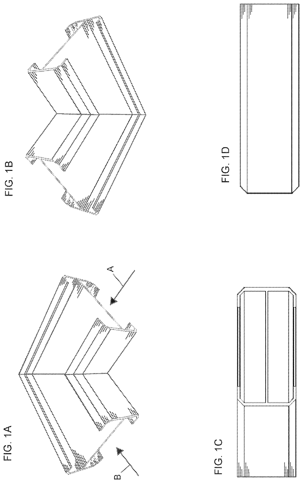
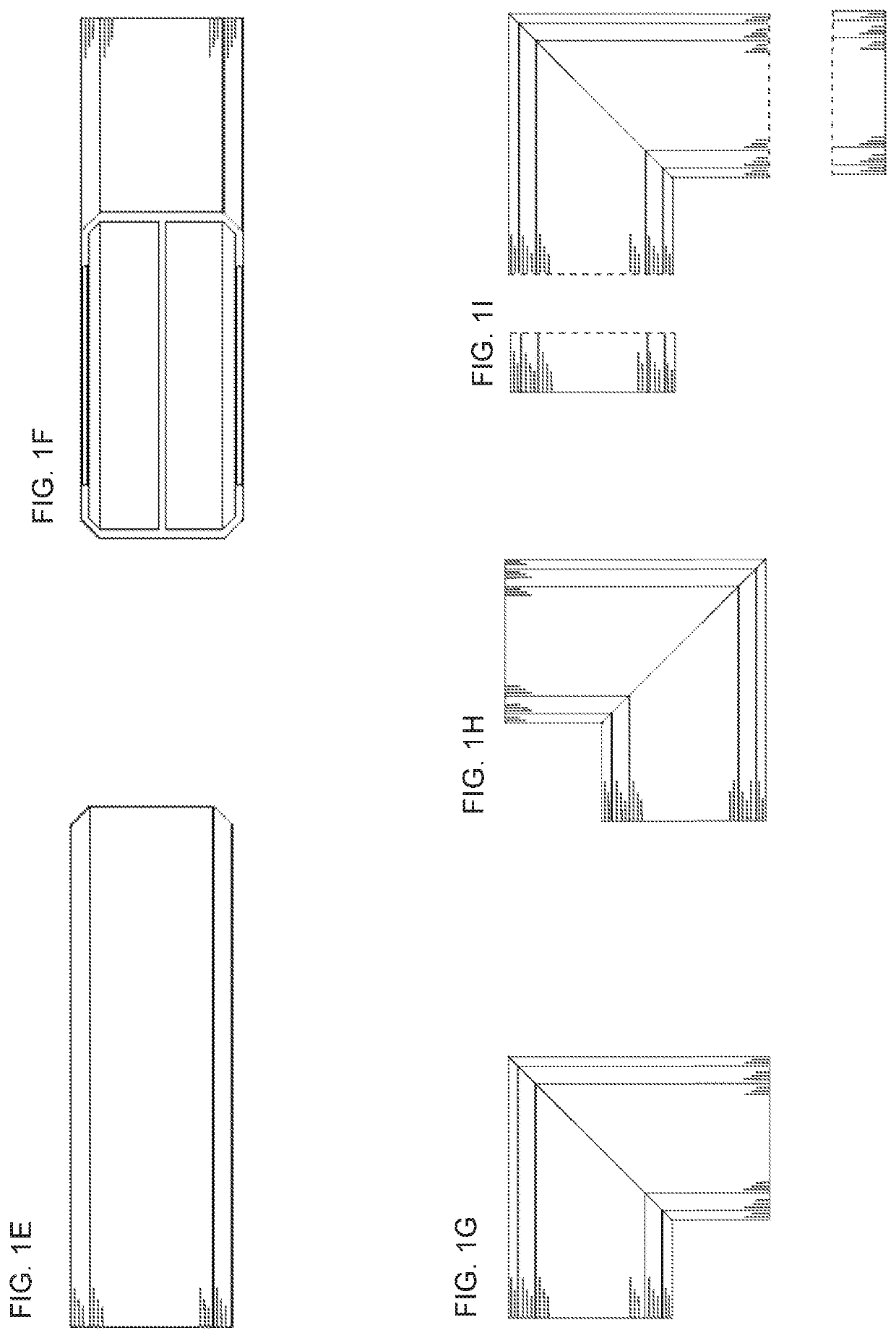
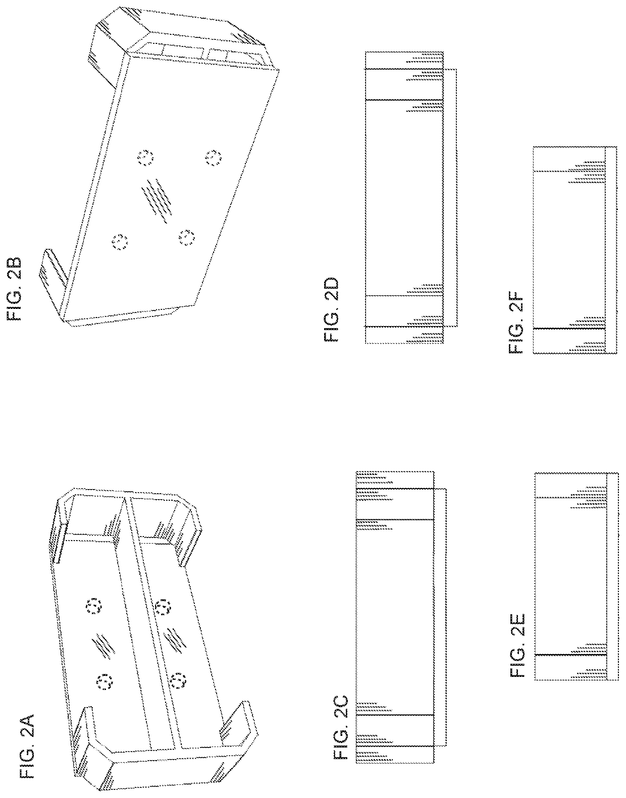
[0131]Referring now to FIGS. 1A-12I, a system and method for constructing a structure 10 is shown. In the illustration being described, the structure 10 defines at least one of a lanai, screen enclosure, carport, walkway cover or other outdoor or indoor framed structure. In the illustration being described, the structure 10 is a lanai frame 12 that supports a mesh screen 14 of the type conventionally known. The structure 10 is a lanai that is attached to a building 16, such as a house, office or other structure, as illustrated in FIGS. 1A-1C. One significant advantage of the structure 10 is that it reduces or eliminates a number of vertical and horizontal beams that were traditionally required in the past so that it provides relatively large viewing areas VA that are unobstructed by beam structure. Of course, the structure 10 also requires fewer beams. Consequently, the structure 10 is less expensive than comparable wide view systems of the past. This is advantageous, for example, w...


PUM


Abstract

A building system that utilizes an improved beam and coupling system for building a frame or structure having improved strength and durability and improving performance and / or spanning distance of the beam.

Description

BACKGROUND OF THE INVENTION1. Field of the Invention[0001]This invention relates to a building system, and more particularly, to a system that utilizes an improved beam and coupling system for building a frame or structure.2. Description of the Related Art[0002]The aluminum enclosure industry and patio screen enclosure roof systems typically utilized beams comprising two identical halves. The halves simply overlap and were stitched or screwed together with a plurality of screws to make one complete self-mating beam. In some applications, an entire extruded one-piece beam was used.[0003]One problem with the prior art beam structures is a high failure rate during strong winds, especially hurricane-force winds. The box beam failed for many reasons including the fact that the beam web was simply overlapped and laid on top of each other. An improved beam system that overcame some problems of the prior art is shown in U.S. Pat. No. 7,877,962; U.S. Design Patent Nos. D620,618; D620,619; D6...

Claims


Application Information

Patent Timeline
IPC IPC(8): E04B1/19E04B1/41E04B1/24
CPCE04B2001/2457E04B2001/2406E04B1/40E04B2001/2421E04B2001/1984E04B1/1906E04B1/2403E04B2001/1933E04B2001/2448E04B2001/1963E04B2001/2451E04B2001/2463E04B1/388
Inventor TEFFENHART, JR., THOMAS JOSEPH
Owner TEFFENHART JR THOMAS JOSEPH
Why Eureka
Try Eureka