Injection unit, with closure pin, for the injection moulding of plastic material, with capacity to recover thermal dilatations and avoid leakage of the plastic material

a technology of injection unit and closure pin, which is applied in the field of injection unit or assembly, to achieve the effect of improving characteristics and performances, avoiding leakage of plastic materials, and effectively recovering different thermal expansions

Active Publication Date: 2022-02-22
THERMOPLAY
View PDF20 Cites 0 Cited by
  • Summary
  • Abstract
  • Description
  • Claims
  • Application Information

AI Technical Summary

Benefits of technology

[0029]Therefore, a first object of the present disclosure is to provide an injection unit or group or assembly, for injection moulding of plastic material, of the specific type comprising a closure pin or rod or needle, also associated with a hot distribution plate having the function of feeding the plastic material in the molten state to the injection unit, and with a control plate which houses the control means for controlling the axial motion of the closure pin, wherein the injection unit exhibits improved characteristics and performances with respect to the injection units already known and in use in the art, and in particular is suitable to effectively recover the different thermal expansions and deformations of the hot distribution plate and the control plate, with which the injection unit is associated, which occur in the operation of the injection unit, so as not to generate dangerous tensions and stresses, in particular on the closure pin of the injection unit, which could affect the correct and regular operation of the injection unit.
[0030]A second object of the present disclosure, however linked to the first one, is that of realizing an injection unit or group, for injection moulding of plastic material, still comprising a closure pin and always associated with a hot distribution plate, having the function of feeding the plastic material in the molten state to the injection unit, and with a control plate, which houses the control means for controlling the axial motion of the closure pin included in the injection unit, wherein the injection unit allows limiting the temperature in the region of a guide bush, of the closure pin, which also acts as a sealing element for the molten plastic material supplied by the hot distribution plate, so as to prevent such plastic material from leaking to the outside of the injection group.
[0031]A further third object of the present disclosure is also that of providing an injection unit for injection moulding of plastic material, still of the type comprising a closure pin, wherein the injection unit is adapted to be easily and quickly assembled in a wider moulding system including a hot distribution plate and a control plate associated with the injection unit, and in particular, during this assembling, is suitable to recover possible errors in the construction and centering of the parts to be assembled together.

Problems solved by technology

Therefore, a first problem that arises in the hot-runner injection moulding technology with the injection nozzles including a closure pin is that of recovering and compensating, i.e. effectively absorbing, the different thermal deformations and expansions of the hot distribution plate and the control plate with which the various injection units are associated, that occur in the operation of the wider moulding system of which the injection units are part and in which they are integrated, in order to avoid that, because to these different thermal deformations and expansions of the hot distribution plate and the control plate, the injection units as a whole and more particularly the closure pin of each single injection unit are subjected to dangerous stresses which might impair the regular operation for controlling the flow of the plastic material in the molten state towards the mould.
Still, a second further problem that always arises in the hot-runner injection moulding technology characterized by injection nozzles including a closure pin is to achieve a good evacuation and transmission of heat from the bush or guide element, in which the closure pin extends and slides axially and which often acts also as a sealing element for the plastic material in the molten state supplied to the injection nozzle, so as to limit the temperature in this area, and therefore avoid that in the guide bush the temperature values are too high which would have the effect of reducing its ability to operate as a sealing element and therefore could cause leakage, through the same guide bush, of the plastic material in the molten state supplied by the hot distribution plate to the injection nozzle.
However, the various solutions offered by the known art, such as those mentioned above and briefly commented on, do not appear, at least in general, completely satisfactory, and all of them one more and one less are affected by limits and drawbacks, so that these known solutions leave room for further improvements.

Method used


Image

  • Injection unit, with closure pin, for the injection moulding of plastic material, with capacity to recover thermal dilatations and avoid leakage of the plastic material
  • Injection unit, with closure pin, for the injection moulding of plastic material, with capacity to recover thermal dilatations and avoid leakage of the plastic material
  • Injection unit, with closure pin, for the injection moulding of plastic material, with capacity to recover thermal dilatations and avoid leakage of the plastic material

Examples


first embodiment

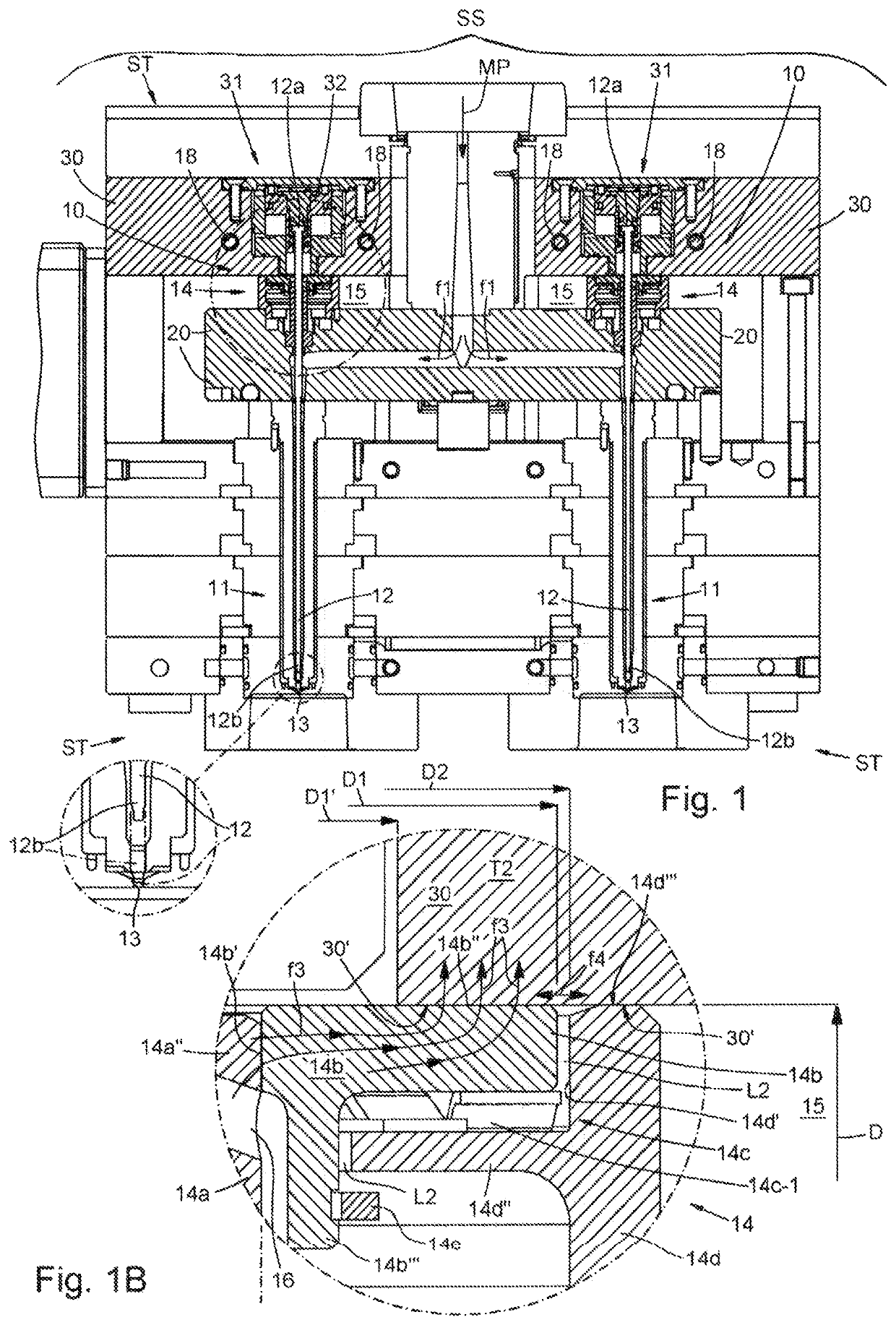
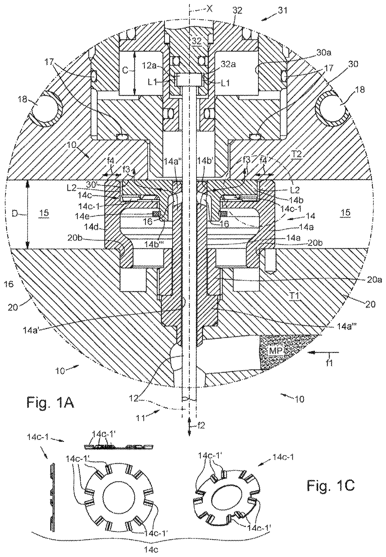
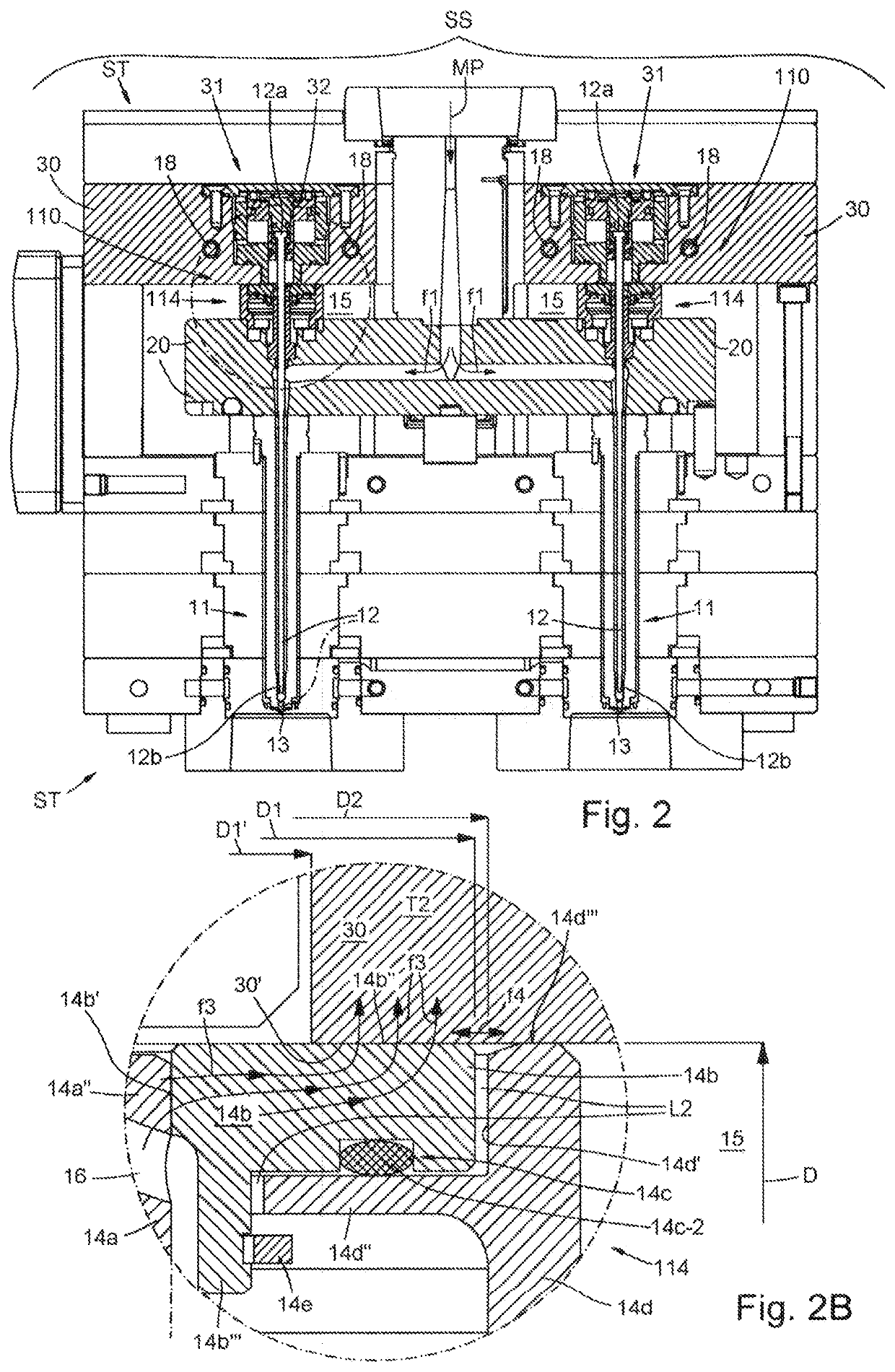
[0052]With reference to the drawings, an injection unit or group or assembly for the injection moulding of plastic material, having the features of the present disclosure and conforming to a first embodiment thereof, is indicated as a whole by 10.

[0053]The injection unit 10 of the disclosure is typically integrated together with other similar injection units or groups 10, into a mould, generally indicated with ST (for example, FIG. 1 shows two of these injection units 10 integrated into the same ST mould) in turn part of a wider moulding system SS, and typically includes:[0054]an injection nozzle 11, extended along a respective axis X and adapted to be fed with a plastic material MP in the molten state, as indicated by an arrow f1; and[0055]a closure needle or pin 12, arranged in the injection nozzle 11 and movable axially back and forth along the respective axis X, as indicated by a double arrow f2, between a first operating position in which the closure pin 12 frees and opens an i...

embodiment 210

[0130]FIG. 3A in turn shows a variant of the configuration of the pressure means 14c which, in the third simplified embodiment 210, are included in the guide and cooling assembly 214 for pressing the cooling ring 14b against the control plate 30, wherein in this variant the pressure means 14c are constituted instead of by a single spring by two or more helical compression springs, indicated with 14c-3′, each mounted around a respective screw 19 fixed to the hot plate 20.

[0131]It is noted that in this variant the screws 19 constitute a not essential element and simply have the function of retaining the springs 14c-3′ in position and facilitating their assembly.

[0132]Again, within the scope of the inventive concept of the present disclosure, other configurations of the guide and cooling assembly, in addition to or as an alternative to those 14, 114, 214 described above, are possible, in order to allow the injection unit, in which the guide and cooling assembly is integrated, both to r...


PUM

PropertyMeasurementUnit
temperatureaaaaaaaaaa

Abstract

Injection unit for injection molding of plastic material including: an injection nozzle; a closure pin; and a guide and cooling assembly, interposed between the back driving plate and the hot distribution plate, in turn comprising: a guide and seal element for guiding the axial motion of the closure pin; a cooling ring; and pressure means configured to press the cooling ring directly and against the back driving plate; wherein the guide and seal element is slidably coupled, at an upper end, with a central hole of the cooling ring, and is fixed integrally, at the other end, to the hot distribution plate; and the cooling ring is able to slide laterally with respect to the back driving plate to recover the differences in thermal expansion between the hot distribution plate and the back driving plate and to transmit heat from the guide and seal element towards the back driving plate.

Description

CROSS-REFERENCE TO RELATED APPLICATIONS[0001]This application claims the benefit of priority of international PCT Patent Application No. PCT / IT2018 / 050126, filed on Jul. 8, 2018, that in turn claims priority to Italian Patent Application No. IT 102017000076433, filed on Jul. 7, 2017, the contents of which are hereby incorporated by reference in their entirety.TECHNICAL FIELD[0002]The present disclosure relates in general to the plastic injection moulding sector, and more particularly it relates to an injection unit or assembly, according to the preamble of the first independent claim, which exhibits better and superior performances than those currently in use and offered in the market, such as an improved ability to recover and absorb the different thermal expansions of the parts of the wider injection system in which the injection unit of the invention is integrated, to reduce the stresses acting on the same injection unit, and to further avoid leakage and losses of the plastic mat...

Claims


Application Information

Patent Timeline
Patent Type & Authority Patents(United States)
IPC IPC(8): B29C45/23B29C45/28B29C45/74
CPCB29C45/231B29C45/2806B29C45/74B29C45/2725B29C2045/2729B29C2045/2733B29C2045/277B29C2045/2889Y02P70/10
Inventor BOSONETTO, GUIDOEMICH, JUERGEN WILHELM
Owner THERMOPLAY
Why Eureka
Try Eureka