Injection unit, with closure pin, for the injection moulding of plastic material, with capacity to recover thermal dilatations and avoid leakage of the plastic material

a technology of injection unit and closure pin, which is applied in the field of injection unit or assembly, to achieve the effect of improving characteristics and performances, avoiding leakage of plastic materials, and effectively recovering different thermal expansions

Active Publication Date: 2020-09-17
THERMOPLAY
View PDF0 Cites 2 Cited by
  • Summary
  • Abstract
  • Description
  • Claims
  • Application Information

AI Technical Summary

Benefits of technology

[0029]Therefore, a first object of the present disclosure is to provide an injection unit or group or assembly, for injection moulding of plastic material, of the specific type comprising a closure pin or rod or needle, also associated with a hot distribution plate having the function of feeding the plastic material in the molten state to the injection unit, and with a control plate which houses the control means for controlling the axial motion of the closure pin, wherein the injection unit exhibits improved characterist...

Problems solved by technology

Therefore, a first problem that arises in the hot-runner injection moulding technology with the injection nozzles including a closure pin is that of recovering and compensating, i.e. effectively absorbing, the different thermal deformations and expansions of the hot distribution plate and the control plate with which the various injection units are associated, that occur in the operation of the wider moulding system of which the injection units are part and in which they are integrated, in order to avoid that, because to these different thermal deformations and expansions of the hot distribution plate and the control plate, the injection units as a whole and more particularly the closure pin of each single injection unit are subjected to dangerous stresses which might impair the regular operation for controlling the flow of the plastic material in the molten state towards the mould.
Still, a second further problem that always arises in the hot-runner injection moulding technology characteri...

Method used


Image

  • Injection unit, with closure pin, for the injection moulding of plastic material, with capacity to recover thermal dilatations and avoid leakage of the plastic material
  • Injection unit, with closure pin, for the injection moulding of plastic material, with capacity to recover thermal dilatations and avoid leakage of the plastic material
  • Injection unit, with closure pin, for the injection moulding of plastic material, with capacity to recover thermal dilatations and avoid leakage of the plastic material

Examples


first embodiment

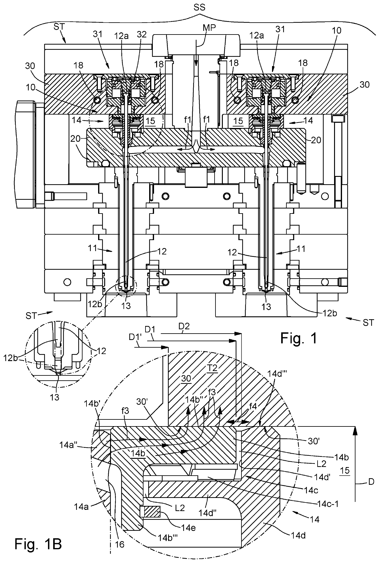
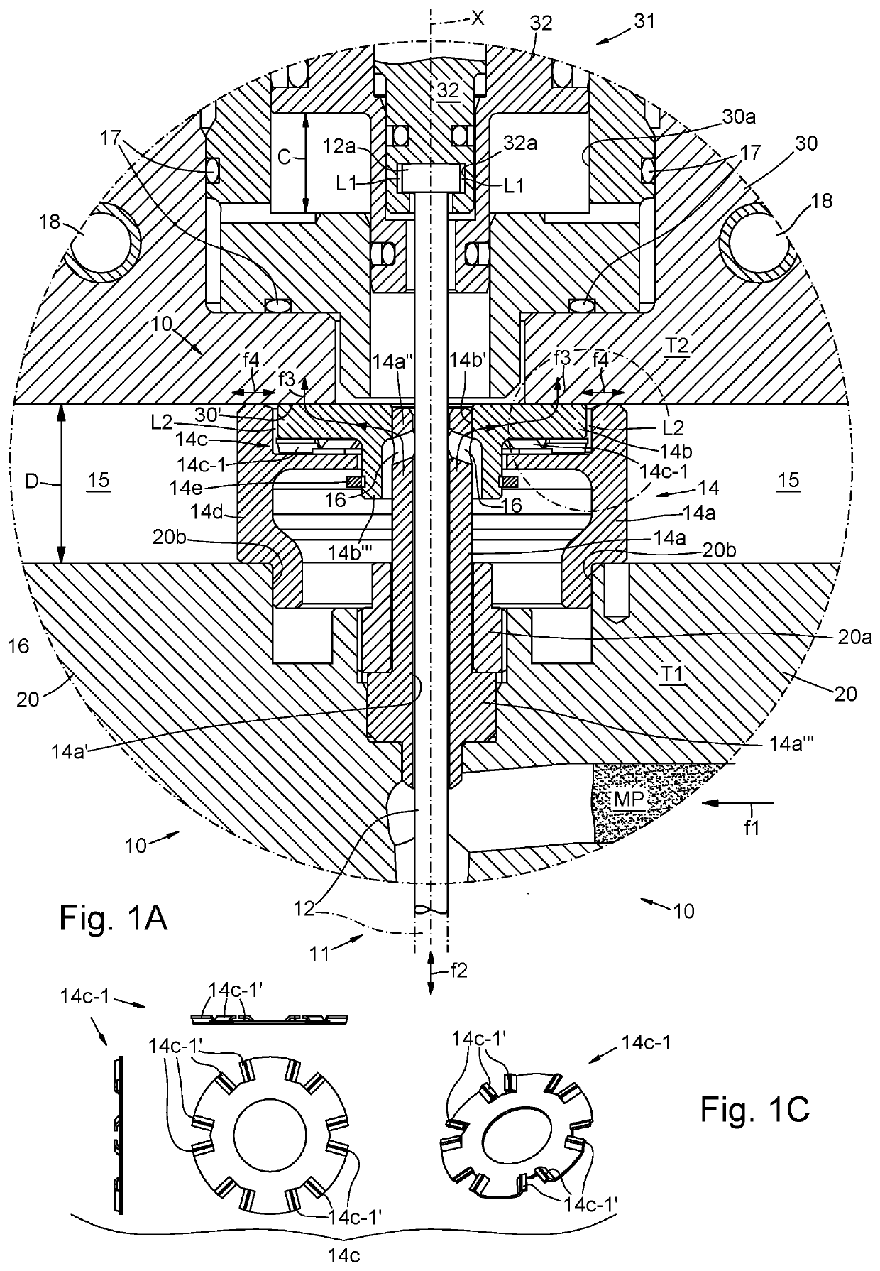
[0051]With reference to the drawings, an injection unit or group or assembly for the injection moulding of plastic material, having the features of the present disclosure and conforming to a first embodiment thereof, is indicated as a whole by 10.

[0052]The injection unit 10 of the disclosure is typically integrated together with other similar injection units or groups 10, into a mould, generally indicated with ST (for example, FIG. 1 shows two of these injection units 10 integrated into the same ST mould) in turn part of a wider moulding system SS, and typically includes:[0053]an injection nozzle 11, extended along a respective axis X and adapted to be fed with a plastic material MP in the molten state, as indicated by an arrow f1; and[0054]a closure needle or pin 12, arranged in the injection nozzle 11 and movable axially back and forth along the respective axis X, as indicated by a double arrow f2, between a first operating position in which the closure pin 12 frees and opens an i...

embodiment 210

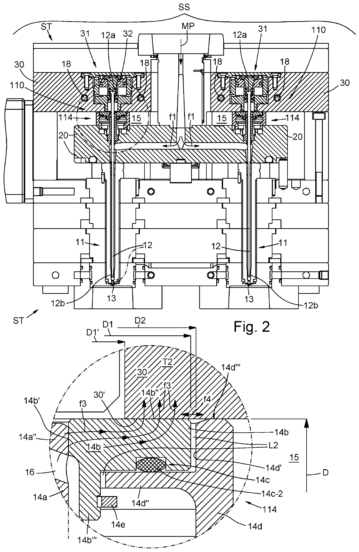
[0125]Therefore, in this embodiment 210, the injection unit of the disclosure, even if it is interposed between the hot distribution plate 20 and the control plate 30, and although the two plates 20 and 30 are mutually spaced by a gap of width D so that they can thermally expand one with respect to the other in their operation, does not receive and consequently does not support and oppose the clamping force which clamps the two plates 20 and 30 together.

[0126]It also follows that, in this third embodiment 210 of the injection unit of the disclosure, the hot distribution plate 20 and the control plate 30 are separated from one another by other parts and elements, distinct from the injection assembly 210, included in the wider moulding system in which the injection assembly 210 is integrated.

[0127]For example, as shown in FIG. 3, the hot distribution plate 20 and the control plate 30 can be separated one from the other by the gap of width D, instead of by the guide and cooling assembl...


PUM

PropertyMeasurementUnit
Pressureaaaaaaaaaa
Diameteraaaaaaaaaa
Areaaaaaaaaaaa

Abstract

Injection unit for injection molding of plastic material including: an injection nozzle; a closure pin; and a guide and cooling assembly, interposed between the back driving plate and the hot distribution plate, in turn comprising: a guide and seal element for guiding the axial motion of the closure pin; a cooling ring; and pressure means configured to press the cooling ring directly and against the back driving plate; wherein the guide and seal element is slidably coupled, at an upper end, with a central hole of the cooling ring, and is fixed integrally, at the other end, to the hot distribution plate; and the cooling ring is able to slide laterally with respect to the back driving plate to recover the differences in thermal expansion between the hot distribution plate and the back driving plate and to transmit heat from the guide and seal element towards the back driving plate.

Description

CROSS-REFERENCE TO RELATED APPLICATIONS[0001]This application claims the benefit of priority of international PCT Patent Application No. PCT / IT2018 / 050126, filed on Jul. 8, 2018, that in turn claims priority to Italian Patent Application No. IT 102017000076433, filed on Jul. 7, 2017, the contents of which are hereby incorporated by reference in their entirety.TECHNICAL FIELD[0002]The present disclosure relates in general to the plastic injection moulding sector, and more particularly it relates to an injection unit or assembly, according to the preamble of the first independent claim, which exhibits better and superior performances than those currently in use and offered in the market, such as an improved ability to recover and absorb the different thermal expansions of the parts of the wider injection system in which the injection unit of the invention is integrated, to reduce the stresses acting on the same injection unit, and to further avoid leakage and losses of the plastic mat...

Claims


Application Information

Patent Timeline
IPC IPC(8): B29C45/23B29C45/74B29C45/28
CPCB29C45/74B29C45/231B29C45/2806B29C45/2725B29C2045/2729B29C2045/2733B29C2045/277B29C2045/2889Y02P70/10
Inventor BOSONETTO, GUIDOEMICH, JUERGEN WILHELM
Owner THERMOPLAY
Why Eureka
Try Eureka