Imprinted micro-louver structure method

a micro-louver and structure technology, applied in the field of micro-louver structures, can solve the problems of difficult to make large micro-louver sheets, difficult to achieve large-scale micro-louver sheets, and limited methods in the depth they can achieve, etc., to achieve the effect of improving transparency, reducing viewing angle, weight, thickness and cos

Inactive Publication Date: 2014-04-24
EASTMAN KODAK CO
View PDF8 Cites 76 Cited by
  • Summary
  • Abstract
  • Description
  • Claims
  • Application Information

AI Technical Summary

Benefits of technology

[0011]There is a need therefore for micro-louver structures and manufacturing methods providing improved transparency and reduced viewing angle, weight, thickness, and cost.
[0019]Structures and methods of the present invention provide improved transparency and reduced viewing angle, weight, thickness, and cost for micro-louver sheets. Improved transparency is provided by enabling reduced micro-louver thickness and fewer layers. Reduced viewing angle is provided by reduced micro-louver thickness, increased micro-louver depth, and multiple micro-louver layers. Reduced weight is provided by reducing the number and thickness of the various layers; reduced cost is achieved through a roll-to-roll manufacturing process that avoids patterned photo-lithographic exposure and etching steps and avoids skiving. Micro-louver sheets of the present invention are useful as privacy screens for display systems in one or two dimensions. In such an application, reduced reflectivity or improved contrast of the micro-louver sheets is desirable, as well as inhibited or restricted display viewing angle.

Problems solved by technology

These methods are limited in the depth they can achieve since photo-lithographic etching has a practical depth limitation or the patterns available are limited to those that can support etching.
Furthermore, photo-lithographic processes are relatively expensive and slow.
It is also difficult to make large micro-louver sheets 12 since it is difficult to cut large, thin sheets, for example using skiving.
Furthermore, such sheets typically need additional processing to remove curl and polish the edges.

Method used


Image

  • Imprinted micro-louver structure method
  • Imprinted micro-louver structure method
  • Imprinted micro-louver structure method

Examples


Embodiment Construction

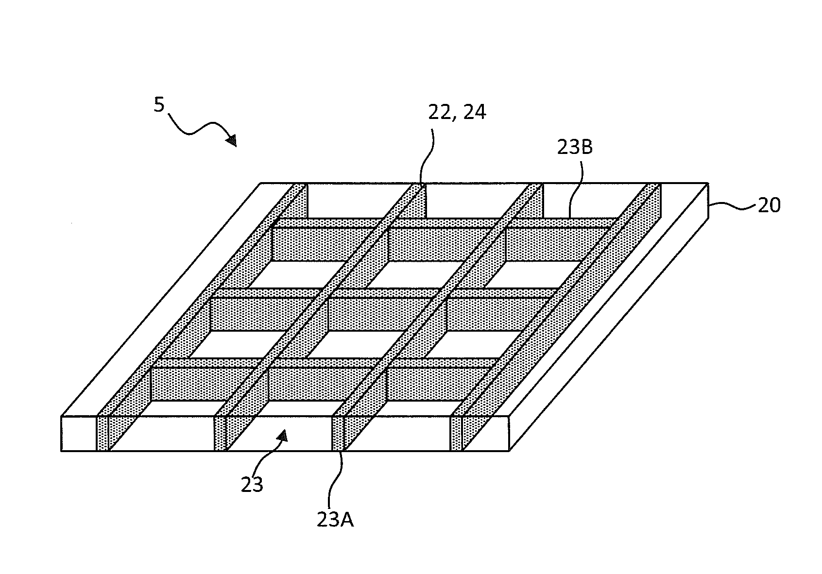
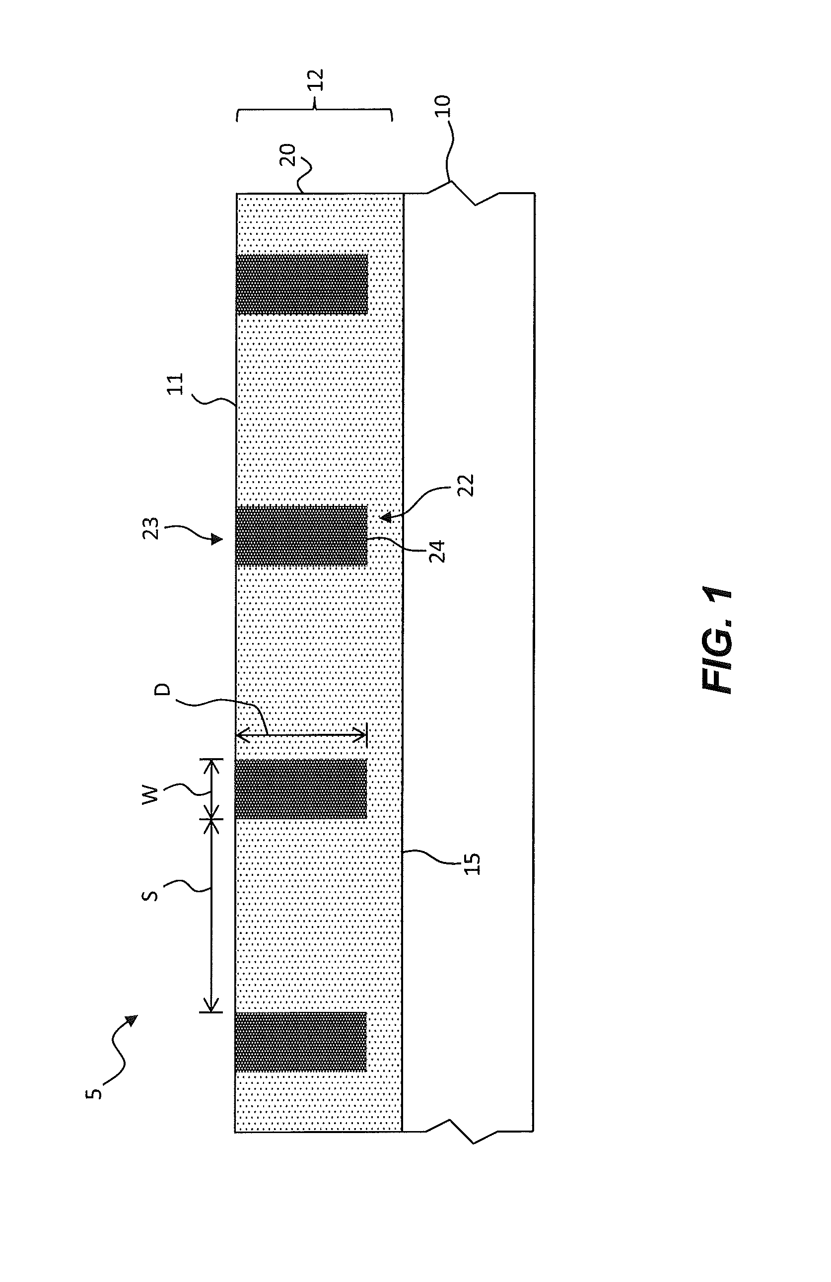
[0032]The present invention is directed to micro-louvers formed in sheets. In an embodiment of the present invention illustrated in FIG. 1, a micro-louver structure 5 includes a cured layer 20 on a surface 15, for example the surface 15 of a substrate 10. The cured layer 20 has a plurality of imprinted micro-channels 22 forming a pattern in the cured layer 20. The imprinted micro-channels 22 have a greater depth D than a width W and are spaced apart by a separation distance S greater than the width W of the imprinted micro-channel 22. A cured light-absorbing material 24 is located in the imprinted micro-channels 22. The cured light-absorbing material 24 in the imprinted micro-channels 22 form micro-louvers 23 in the micro-louver sheet 12 including the cured layer 20.

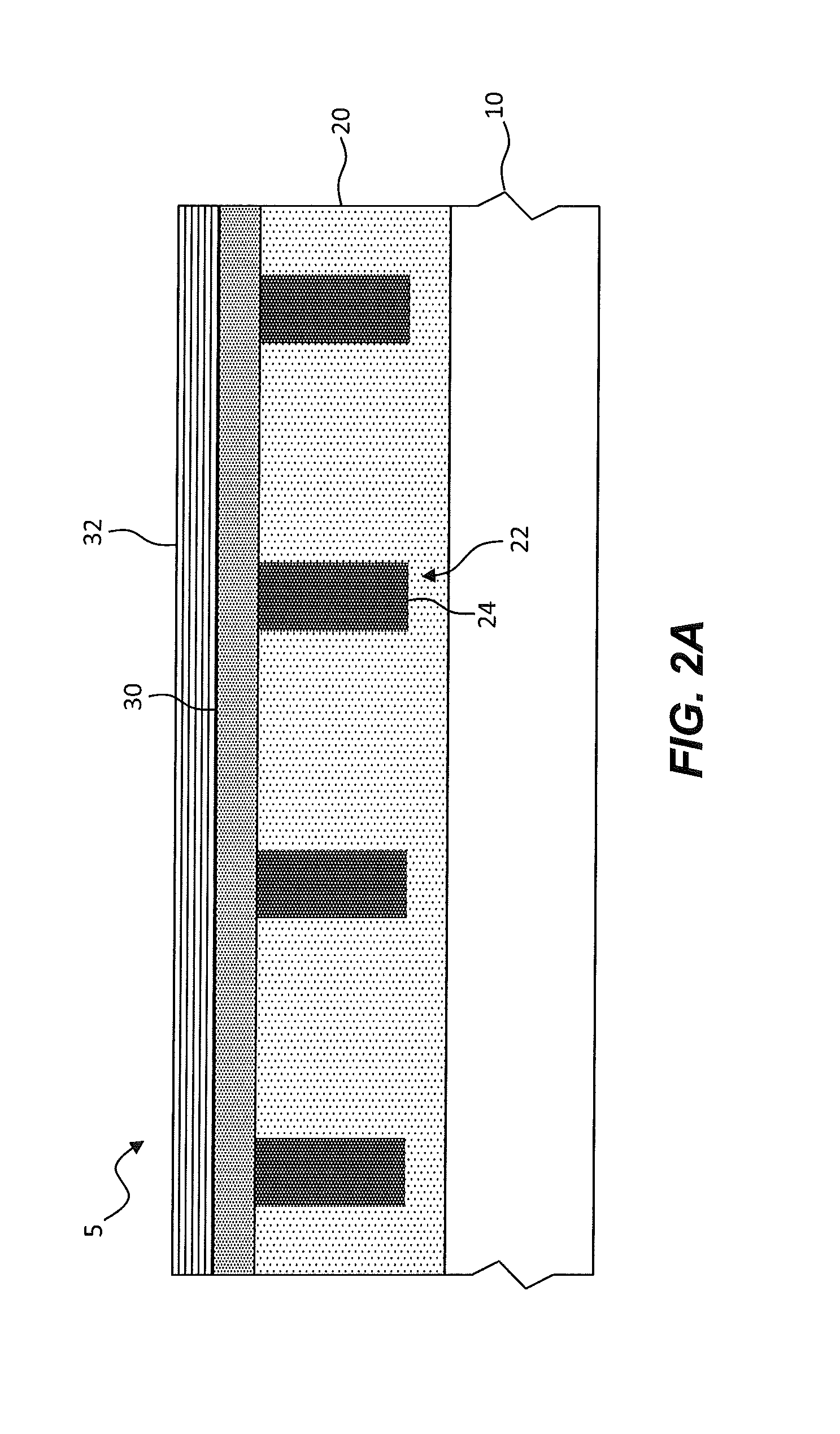
[0033]In an embodiment, the cured layer 20 is formed on the surface 15 of the substrate 10. In another embodiment, the imprinted micro-channels 22 and the cured light-absorbing material 24 extend only partially through t...


PUM

PropertyMeasurementUnit
widthaaaaaaaaaa
widthaaaaaaaaaa
widthaaaaaaaaaa

Abstract

A method of making a micro-louver structure includes coating a curable layer on a surface and imprinting a pattern of micro-channels in the curable layer. The micro-channels have a greater depth than width and are spaced apart by a separation distance greater than the width. The curable layer is at least partially cured to form a cured layer. A light-absorbing material is coated over the cured layer and in the micro-channels and at least a portion of the light-absorbing material removed from the surface of the cured layer leaving at least a portion of the light-absorbing material in the micro-channels. The light-absorbing material is cured to form a light-absorbing structure in each micro-channel.

Description

CROSS REFERENCE TO RELATED APPLICATION[0001]Reference is made to commonly-assigned U.S. patent application Ser. No. ______ filed concurrently herewith, entitled “Imprinted Micro-Louver Structure” by Ronald S. Cok, the disclosure of which is incorporated herein.FIELD OF THE INVENTION[0002]The present invention relates to micro-louver structures.BACKGROUND OF THE INVENTION[0003]Micro-louver structures are widely used for privacy screens to inhibit display viewing at large angles from an angle orthogonal to the display. Micro-louver structures are also useful for rejecting specular illumination of a surface at large angles from an angle orthogonal to the surface. For example, U.S. Pat. No. 5,543,870 describes a rear-projection screen with two crossed films of micro-louver light control material to provide a high degree of blocking of high-intensity light, such as sunlight that can impinge upon the front of the screen. U.S. Patent Application Publication 20090242142 describes a vertical...

Claims


Application Information

Patent Timeline
Patent Type & Authority Applications(United States)
IPC IPC(8): G02B6/00
CPCG02B6/00G02F1/133524G06F21/84G02B5/001G02B2207/123Y10T156/1002C23C16/45525G02B5/1857G02B5/3058H01L21/0274H01L21/31138
Inventor COK, RONALD STEVEN
Owner EASTMAN KODAK CO
Why Eureka
Try Eureka