Dual Current Path For High Rated Currents

a technology of rated current and dual current path, which is applied in the direction of high-tension/heavy-dress switches, contacts, air-break switches, etc., can solve the problems of substantial modification of existing equipment, limited maximum possible continuous rated current for circuit breakers, and relatively high cost solutions, so as to increase the cooling surface, reduce resistance, and increase the surface area available

Active Publication Date: 2014-04-24
HITACHI ENERGY SWITZERLAND AG
View PDF3 Cites 1 Cited by
  • Summary
  • Abstract
  • Description
  • Claims
  • Application Information

AI Technical Summary

Benefits of technology

[0016]One gist of the present invention is to provide a current path section arrangement that has an increased surface area available for cooling of the current path section, e.g. by means of convection, and a decreased resistance compared to e.g. a circuit breaker comprising a circuit breaker module for effectuating interruption of the current and a current path section comprising a single member connecting the circuit breaker module to the electrical circuit.
[0017]In contrast to a current path section comprising a single member, the current path section arrangement according to the present invention includes two or more current path section members arranged relatively to each other so as to be able to increase the cooling surface and decrease resistance of the overall current path section arrangement. This is achieved by the at least one second current path section member being arranged in spaced relation to a surface of the first current path section member, which a

Problems solved by technology

In general, the maximum possible continuous rated current for a circuit breaker is limited by the choice of material in the current carrying parts in the circuit breaker.
However, by the arrangement of the current paths sections relatively to th

Method used


Image

  • Dual Current Path For High Rated Currents
  • Dual Current Path For High Rated Currents
  • Dual Current Path For High Rated Currents

Examples


Embodiment Construction

[0066]The present invention will now be described more fully hereinafter with reference to the accompanying drawings, in which exemplifying embodiments of the present invention are shown. The present invention may, however, be embodied in many different forms and should not be construed as limited to the embodiments set forth herein; rather, these embodiments are provided by way of example so that this disclosure will convey the scope of the present invention to those skilled in the art. Furthermore, like numbers refer to like or similar elements or components throughout.

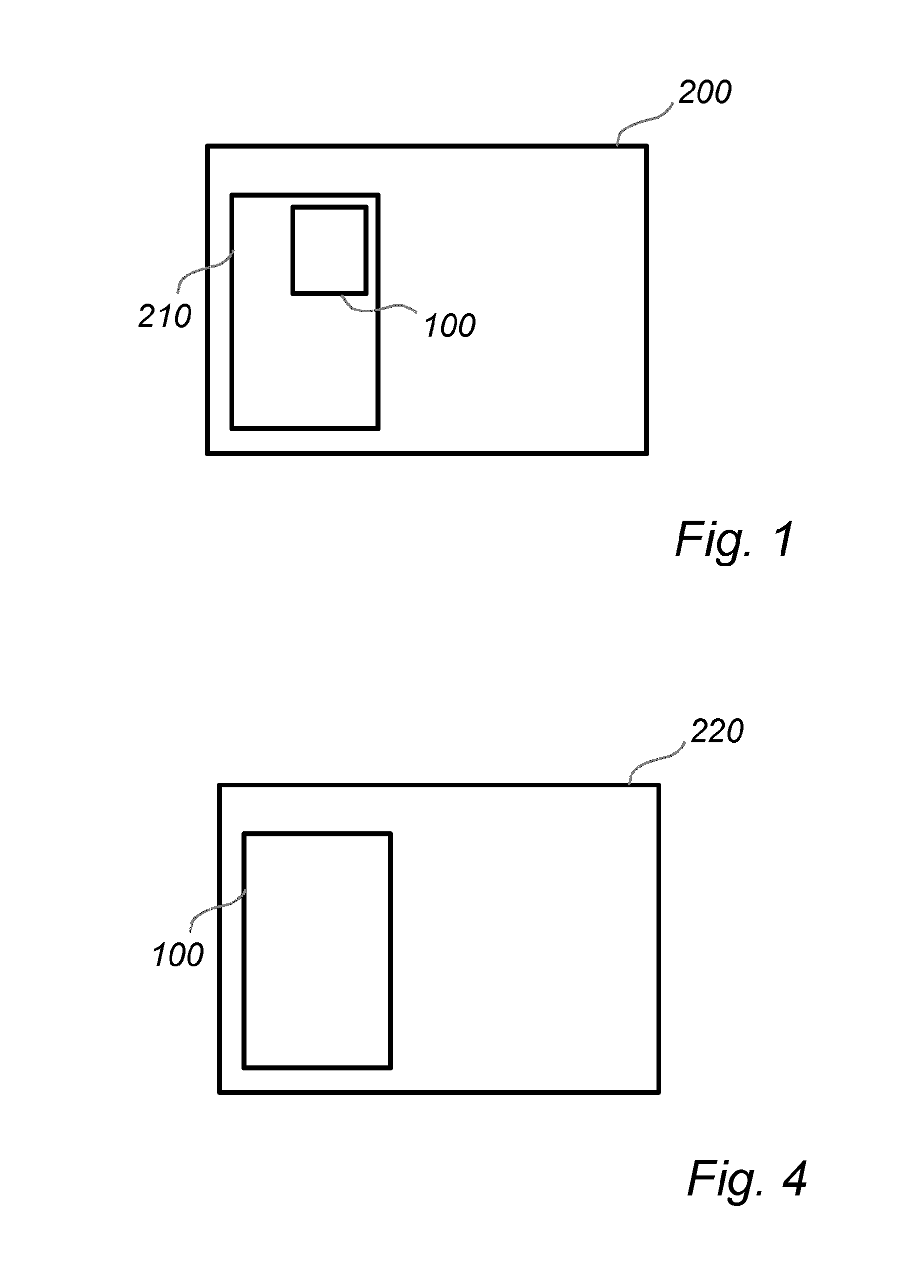
[0067]Referring now to FIG. 1, there is shown a schematic block diagram of an electrical power transmission system 200 according to an exemplifying embodiment of the present invention. The electrical power transmission system 200 comprises an electrical circuit 210 to which a circuit breaker 100 according to an embodiment of the present invention is connected.

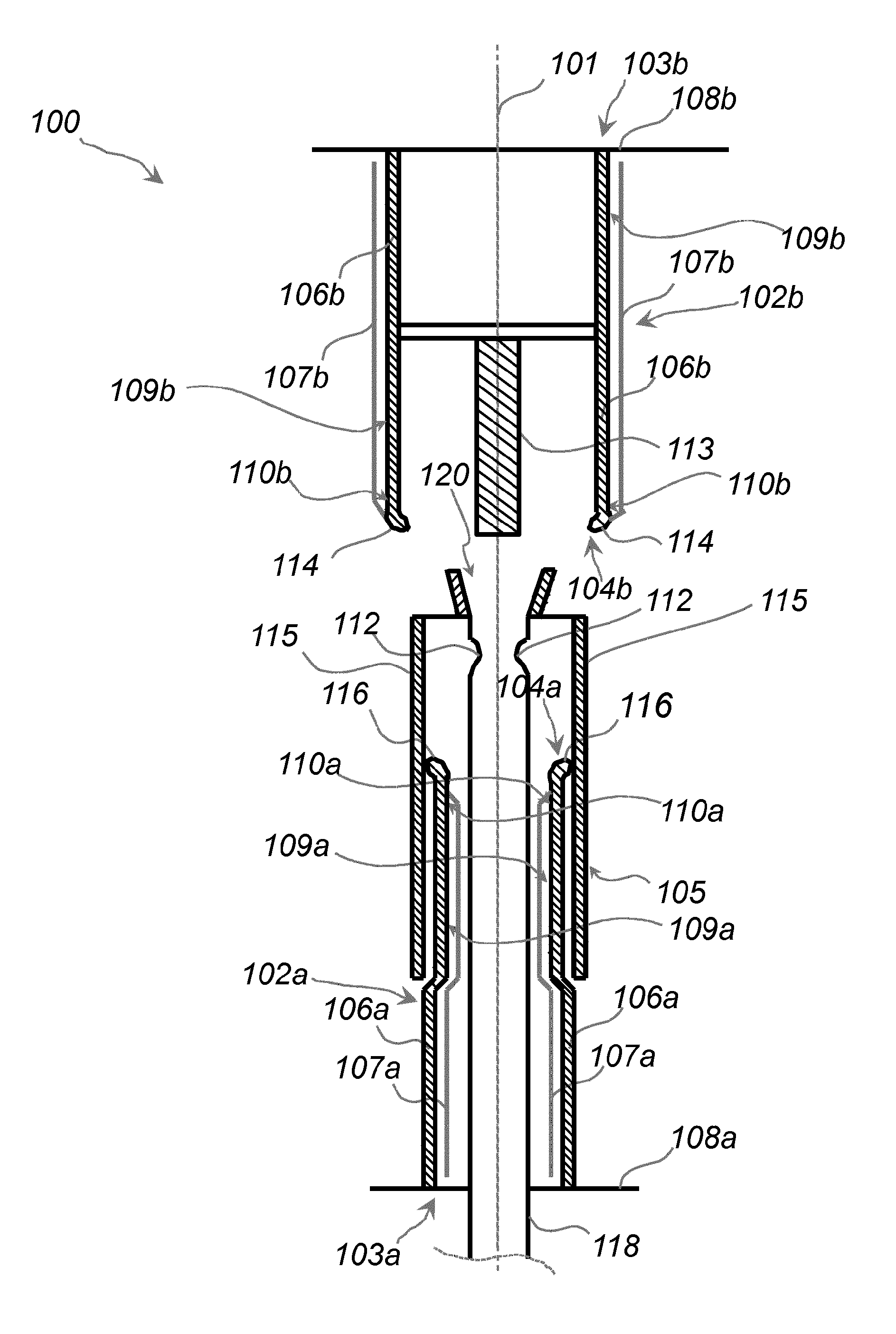
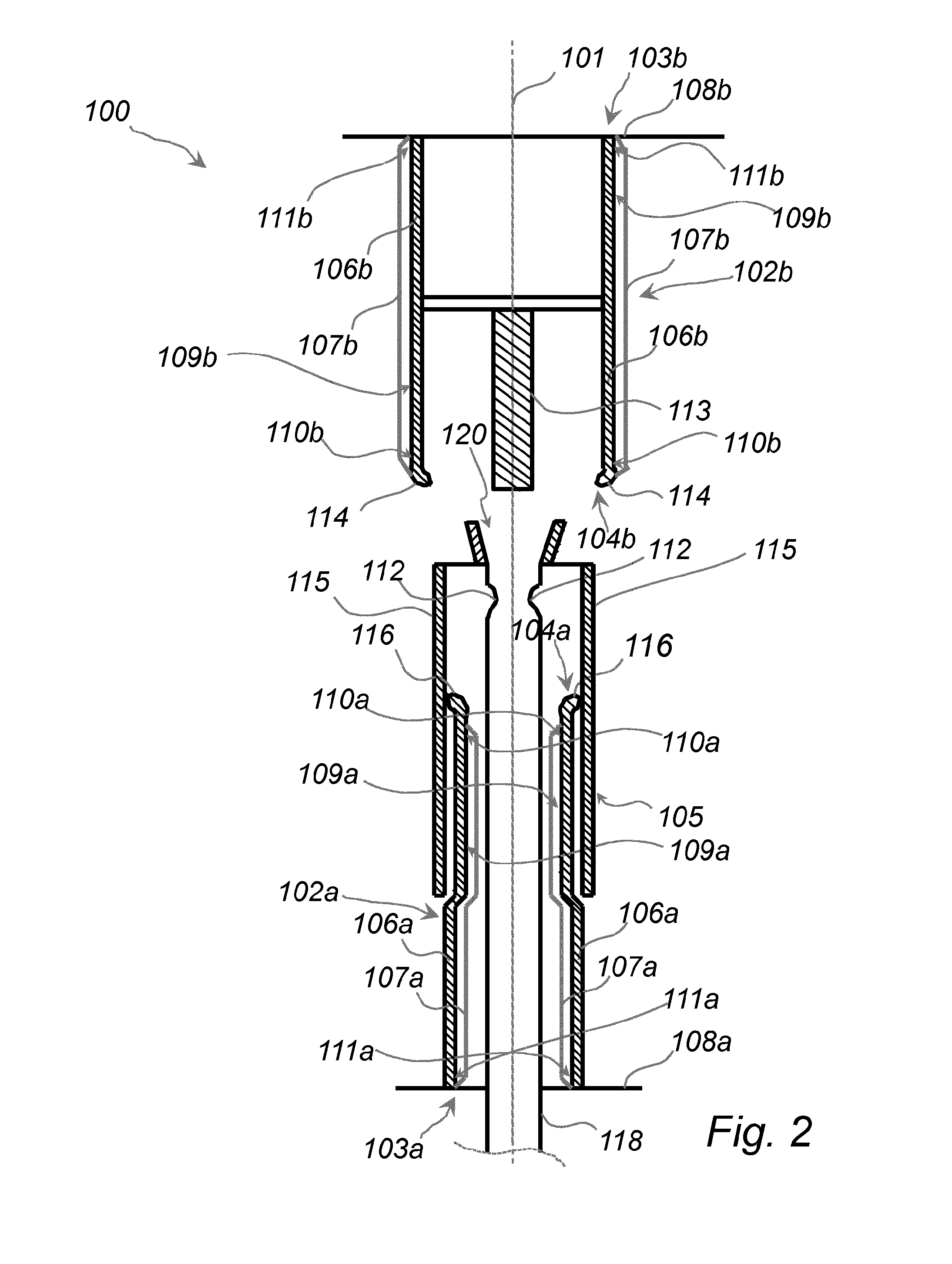
[0068]Referring now to FIG. 2, there is shown a schematic...


PUM


Abstract

A circuit breaker is disclosed. The circuit breaker includes a first current path section and a second current path section. At least one of the first and second current path section includes a first current path section member and at least one second current path section member. The at least one second current path section member is arranged in spaced relation to a surface of the first current path section member. The at least one second current path section member is electrically coupled with the first current path section member via at least a first coupling surface portion of the surface of the first current path section member.

Description

FIELD OF THE INVENTION[0001]The present invention generally relates to equipment used in electrical power transmission. Specifically, the present invention relates to a circuit breaker, which may be particularly suitable for high voltage electrical power transmission systems.BACKGROUND OF THE INVENTION[0002]Circuit breakers for interrupting an electrical circuit, i.e. discontinuing flow of electrical current in the electrical circuit, are known. Such circuit breakers are arranged in the respective electrical circuits which are intended to be interrupted based on some predefined event occurring in the electrical circuit. Generally, operation of such circuit breakers are responsive to detection of a fault condition or fault current. On detection of such a fault condition or fault current, a mechanism may operate the circuit breaker so as to interrupt the current flowing therethrough, thereby interrupting the current flowing in the electrical circuit. Typically, once a fault is detecte...

Claims


Application Information

Patent Timeline
IPC IPC(8): H01H33/02
CPCH01H33/02H01H1/385H01H33/025H01H33/14H01H33/91
Inventor AKESSON, ULF
Owner HITACHI ENERGY SWITZERLAND AG
Why Eureka
Try Eureka