Optical Imaging System for Pickup

an optical imaging system and optical imaging technology, applied in optics, instruments, lenses, etc., can solve the problems that the total length of the optical imaging system cannot be reduced, and the total length of the optical imaging system still fails to meet the specifications of compact electronic devices, so as to reduce the total length, and good aberration correction

Active Publication Date: 2014-04-24
LARGAN PRECISION
View PDF1 Cites 26 Cited by
  • Summary
  • Abstract
  • Description
  • Claims
  • Application Information

AI Technical Summary

Benefits of technology

[0022]With the arrangement of the aforementioned first lens element, second lens element, third lens element, fourth lens element, fifth lens element and sixth lens element with an appropriate interval apart from one another, the present disclosure can provide a good aberration correction and an advantageous modulation transfer function (MTF) in a greater field of view.
[0023]In the optical imaging system for pickup of the present disclosure, the first lens element with positive refractive power provides most of the refractive power required to assist reducing the total length, and the second lens element with negative refractive power can correct aberrations produced by the lens element with positive refractive power effectively and correct the Petzval sum of the system to make the image surface on the edge flatter. If the second lens element has a concave image-side surface, the intensity of negative refractive power of the second lens element can be adjusted appropriately according to the surface shape to provide a good aberration correction effect to the system. In addition, the meniscus fourth lens element and fifth lens element having a concave object-side surface and a convex image-side surface can assist the aberration correction. The curvature ratio at the periphery of the image-side surface facilitates suppressing the angle of projecting the light onto the sensor to enhance the light sensitivity of the image sensor. With the complementary fifth lens element with positive refractive power and sixth lens element with negative refractive power, the telecentric effect can be achieved to facilitate reducing the rear focal length, so as to shorten the total length.
[0024]In the optical imaging system for pickup of the present disclosure, the arrangement of the stop produces a longer distance between the exit pupil of the optical imaging system for pickup and the image plane so that the imaging light can be projected directly and then received by the image sensor to avoid dark corners or achieve the telecentric effect on the image side. In general, the telecentric effect can improve the brightness of the image plane and enhance the speed of receiving images by the CCD or CMOS image sensor.
[0025]In the optical imaging system for pickup of the present disclosure, the combination of the first lens element with positive refractive power, the second lens element with negative refractive power and the third lens element with positive or negative refractive power, and the mutual compensation of the fifth lens element with positive refractive power and the sixth lens element with negative refractive power can reduce the total length of the optical imaging system for pickup effectively, so that the image sensor can have a larger effective pixel range within the same total length. In other words, a shorter optical imaging system for pickup can be designed with the same effective pixel range of the image sensor.
[0026]If the sixth lens element has an inflection point, the inflection point can be used for guiding imaging light with an angle out from the edges of the fifth lens element, such that the imaging light at the off-axis view angle is guided to the image sensor and received by the image sensor. In addition, the optical imaging system for pickup includes at least three lens elements made of plastic to facilitate the manufacture with lower costs.

Problems solved by technology

As disclosed in U.S. Pat. Nos. 7,701,649, 4,389,099, and 4,550,987, adopting the optical imaging systems tend to have a good aberration correction, but the total length of the optical imaging system for pickup still fails to satisfy the specifications for compact electronic devices.
These conventional designs must increase the rear focal length of the optical imaging system for pickup, so that the total length of the optical imaging system cannot be reduced.

Method used


Image

  • Optical Imaging System for Pickup
  • Optical Imaging System for Pickup
  • Optical Imaging System for Pickup

Examples


first preferred embodiment

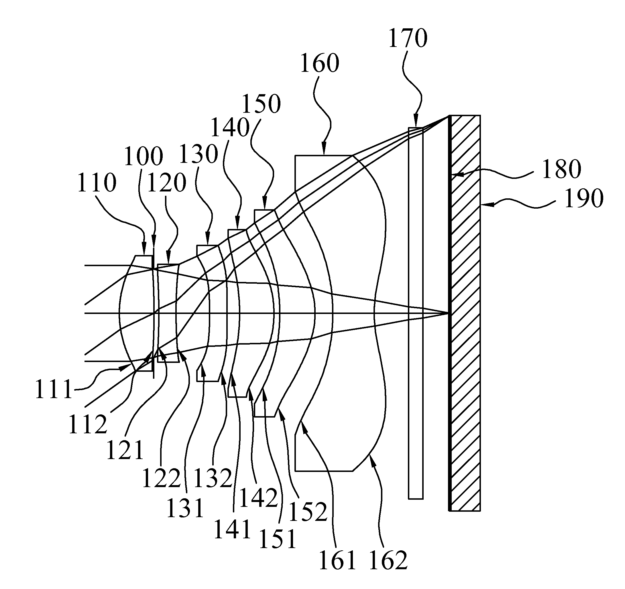
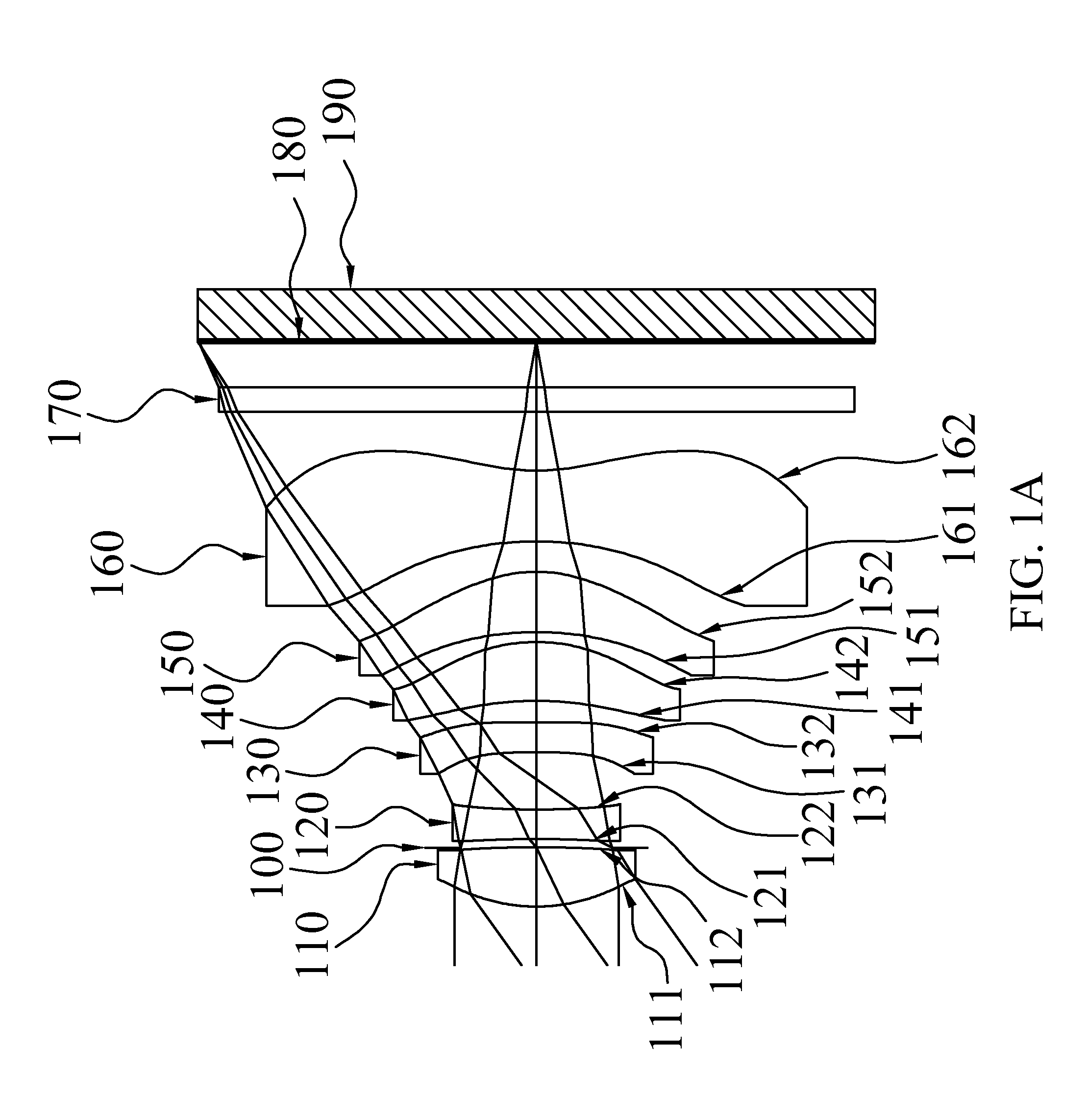
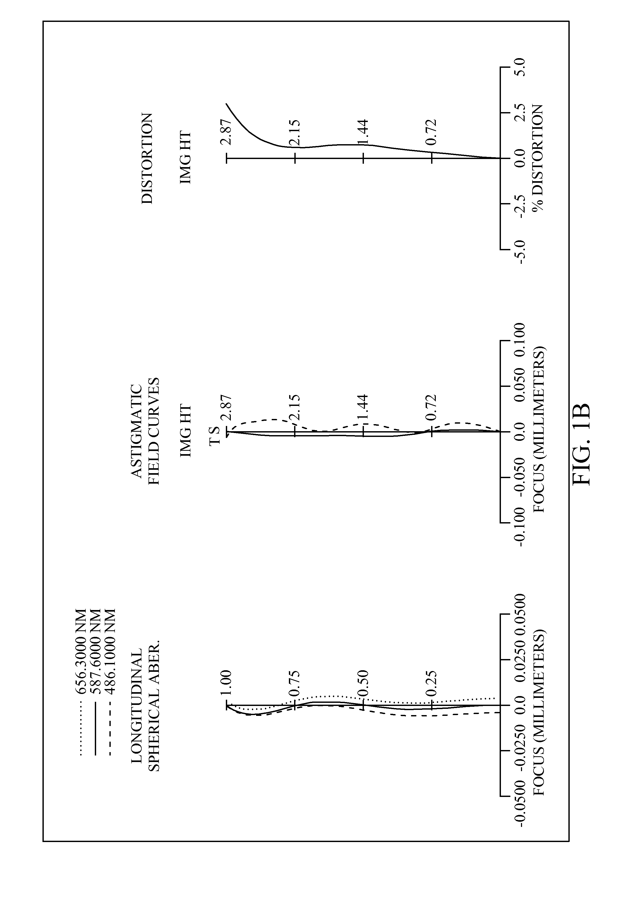
[0054]With reference to FIGS. 1A and 1B for a schematic view and a series of aberration curves of an optical imaging system for pickup in accordance with the first preferred embodiment of the present disclosure respectively, the optical imaging system for pickup comprises six lens elements, a stop and an IR-filter 170. More specifically, the stop can be an aperture stop 100, and the optical imaging system for pickup, sequentially arranged from an object side to an image side along an optical axis, comprises: the plastic first lens element 110 with positive refractive power having a convex object-side surface 111, and a convex image-side surface 112, and both object-side surface 111 and image-side surface 112 being aspheric; an aperture stop 100; the plastic second lens element 120 with negative refractive power having a concave object-side surface 121 and a concave image-side surface 122, both object-side surface 121 and image-side surface 122 being aspheric; the plastic third lens ...

second preferred embodiment

[0058]With reference to FIGS. 2A and 2B for a schematic view and a series of aberration curves of an optical imaging system for pickup in accordance with the second preferred embodiment of the present disclosure respectively, the optical imaging system for pickup comprises six lens elements, a stop and an IR-filter 270. More specifically, the stop can be an aperture stop 200, and the optical imaging system for pickup, sequentially arranged from an object side to an image side along an optical axis, comprises: the plastic first lens element 210 with positive refractive power having a convex object-side surface 211, and a convex image-side surface 212, and both object-side surface 211 and image-side surface 212 being aspheric; an aperture stop 200; the plastic second lens element 220 with negative refractive power having a concave object-side surface 221 and a concave image-side surface 222, both object-side surface 221 and image-side surface 222 being aspheric; the plastic third lens...

third preferred embodiment

[0062]With reference to FIGS. 3A and 3B for a schematic view and a series of aberration curves of an optical imaging system for pickup in accordance with the third preferred embodiment of the present disclosure respectively, the optical imaging system for pickup comprises six lens elements, a stop and an IR-filter 370. More specifically, the stop can be an aperture stop 300, and the optical imaging system for pickup, sequentially arranged from an object side to an image side along an optical axis, comprises: an aperture stop 300; the plastic first lens element 310 with positive refractive power having a convex object-side surface 311, and a concave image-side surface 312, and both object-side surface 311 and image-side surface 312 being aspheric; the plastic second lens element 320 with negative refractive power having a convex object-side surface 321 and a concave image-side surface 322, both object-side surface 321 and image-side surface 322 being aspheric; the plastic third lens ...


PUM


Abstract

An optical imaging system for pickup, sequentially arranged from an object side to an image side, including: the first lens element with positive refractive power having a convex object-side surface, the second lens element with refractive power, the third lens element with refractive power, the fourth lens element with refractive power, the fifth lens element with refractive power; the sixth lens element made of plastic, the sixth lens with refractive power having a concave image-side surface with both being aspheric, and the image-side surface having at least one inflection point.

Description

CROSS-REFERENCE TO RELATED APPLICATION[0001]This application is a continuation of application Ser. No. 13 / 333,139, filed Dec. 21, 2011, which claims priority to Taiwan Patent Application No. 100121391, filed on Jun. 20, 2011, in the Taiwan Intellectual Property Office, the disclosure of which is incorporated herein in its entirety by reference.BACKGROUND[0002]1. Technical Field[0003]The present disclosure relates to an optical imaging system for pickup, and more particularly to the optical imaging system for pickup comprised of six lens elements to shorten total length and improve image quality for applying to electronic products.[0004]2. Description of the Related Art[0005]In compact electronic products such as digital still cameras, or mobile phone cameras, an optical imaging system for pickup is generally installed for capturing images of an object, and the optical imaging system for pickup tends to be developed with a compact design and a low cost, while meeting the user require...

Claims


Application Information

Patent Timeline
Patent Type & Authority Applications(United States)
IPC IPC(8): G02B13/00
CPCG02B13/0045G02B9/62G02B13/18G02B3/04H04N23/13H04N25/00H04N25/71H04N25/76G02B27/0025G02B5/208
Inventor HUANG, HSIN-HSUAN
Owner LARGAN PRECISION
Why Eureka
Try Eureka