
Image processing device, image processing method and control program

a control program and image processing technology, applied in the field of image processing devices, image processing methods, control programs for retrieval of images, can solve the problems of not so many users who correctly understand logical expressions, perform unnecessary retrieval, and difficult intuitive retrieval for users using query images

Inactive Publication Date: 2014-04-24
ORMON CORP
View PDF7 Cites 8 Cited by
  • Summary
  • Abstract
  • Description
  • Claims
  • Application Information

AI Technical Summary

Benefits of technology

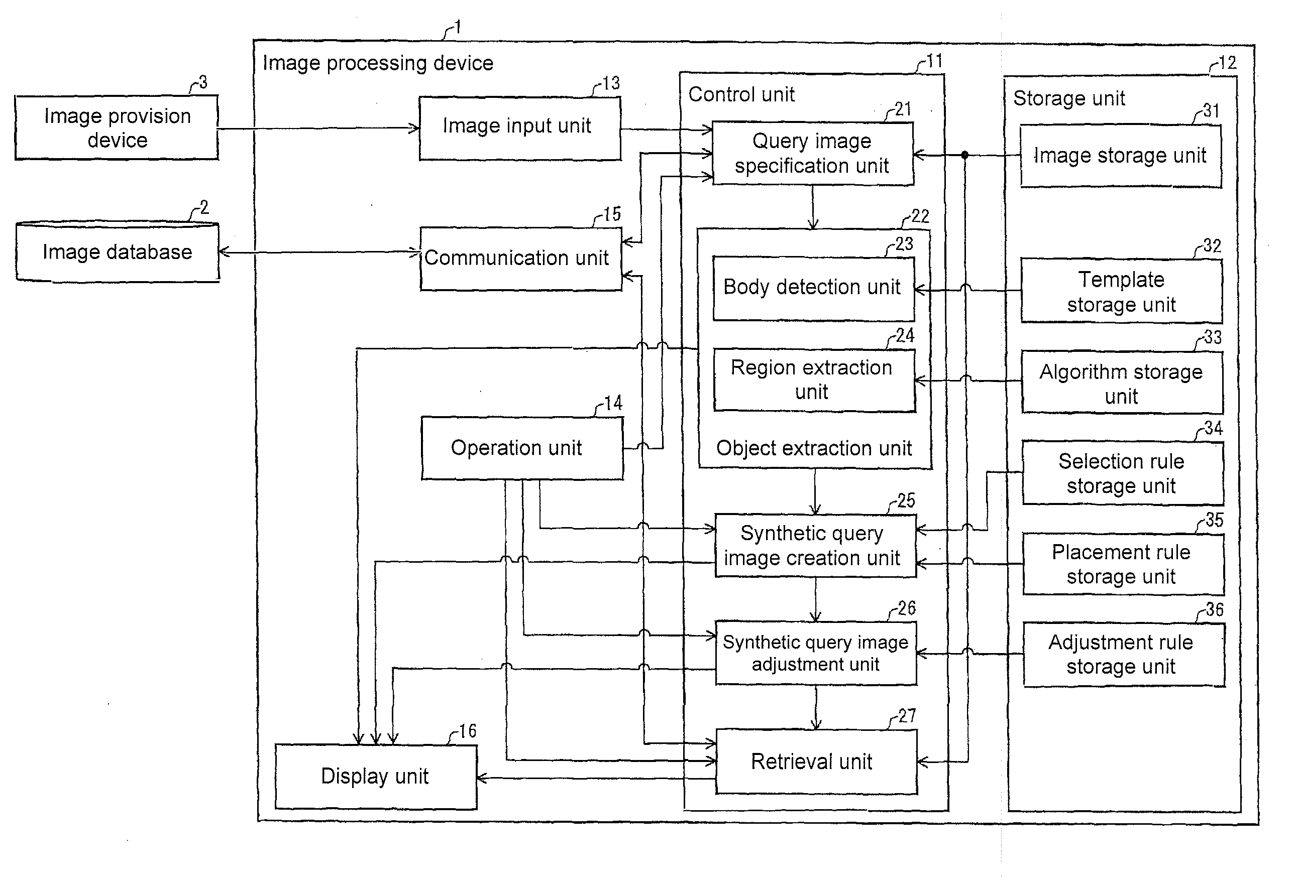
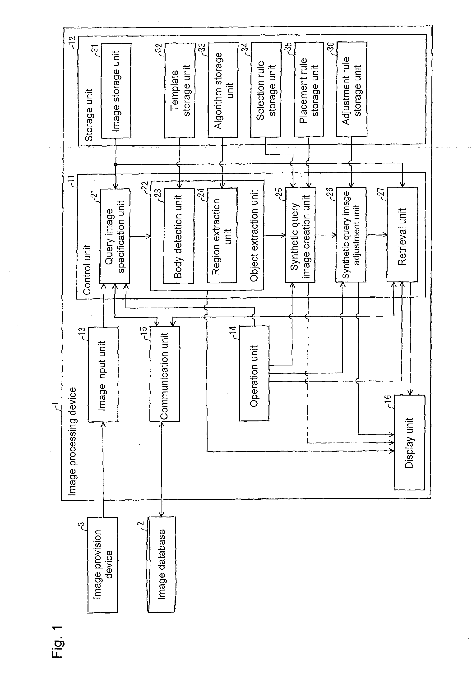
This patent describes an image processing system that can automatically detect objects in a user's image, and efficiently retrieve similar images using a synthetic query image including the detected objects. This reduces the processing load on the system and makes it easier for users to retrieve the desired image.

Problems solved by technology

Thus, the image processing device described in Patent Document 2 performs unnecessary retrieval.
Typically, there are not so many users who correctly understand a logical expression.
According to the technique described in Patent Document 2, it is difficult for a user to intuitively retrieve with use of query images.

Method used


Image

  • Image processing device, image processing method and control program
  • Image processing device, image processing method and control program
  • Image processing device, image processing method and control program

Examples


example 1

[Display Screen Example 1]

[0097]Examples of display screens displayed on the display unit 16 during the image retrieval processing are described next based on FIGS. 5(a) to 5(d) and 6(a) to 6(d). FIGS. 5(a) to 5(d) and 6(a) to 6(d) exemplify the display screens displayed on the display unit 16 during the image retrieval processing. In the examples shown in FIGS. 5(a) to 5(d) and 6(a) to 6(d), assume that a user selects, as a query image, an image obtained by the image input unit 13 from the image provision device 3. Furthermore, assume that the object extraction unit 22 extracts one object that is most featured in each query image and the synthetic query image creation unit 25 selects an object to be pasted in accordance with a user's command.

[0098]As shown in FIG. 5(a), the control unit 11 initially causes an inputted image P1 obtained by the image input unit 13 from the image provision device 3 to be displayed on the display unit 16. If the user selects with use of the operation u...

example 2

[Display Screen Example 2]

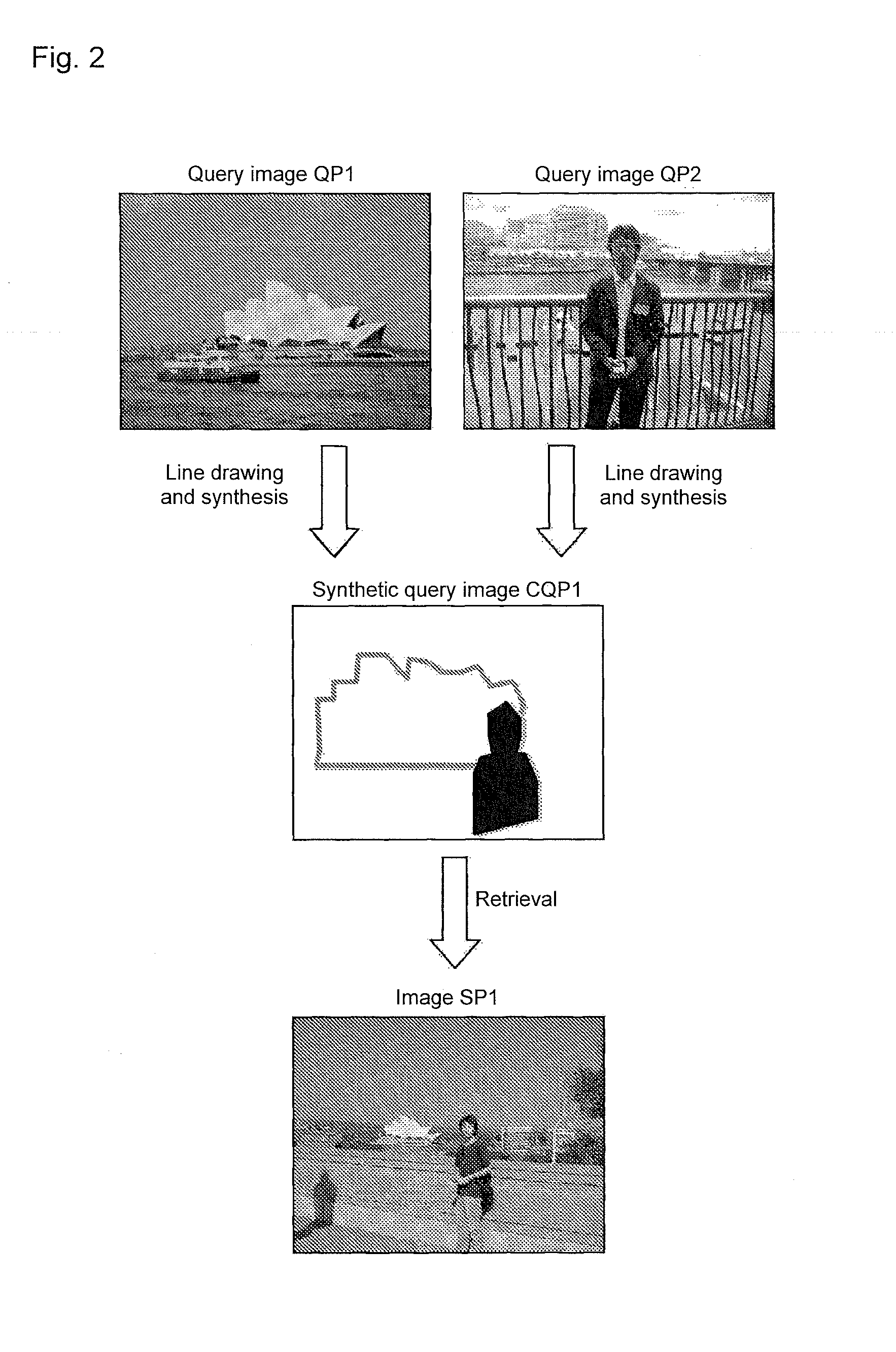
[0105]Other examples of display screens displayed on the display unit 16 during the image retrieval processing are described next based on FIGS. 7(a) and 7(b). FIGS. 7(a) and 7(b) exemplify the different display screens displayed on the display unit 16 during the image retrieval processing. In the examples shown in FIGS. 7(a) and 7(b), assume that a user selects, as query images, the images P1 and P2 obtained by the image input unit 13 from the image provision device 3. Furthermore, assume that the object extraction unit 22 extracts a plurality of objects from the respective query images and the synthetic query image creation unit 25 automatically selects objects to create a synthetic query image.

[0106]The object extraction unit 22 extracts objects from each of the query images QP1 and QP2, and causes objects OBJ1, OBJ3, and OBJ4 extracted from the query image QP1 and objects OBJ2 and OBJ5 extracted from the query image QP2 to be displayed on the display un...


PUM


Abstract

An image processing device has a query image specification unit that specifies a query image in accordance with designation by a user, an object detection unit that detects an object in the query image, a synthetic query image generation unit that synthesizes a plurality of objects in the objects detected by the object detection unit to generate a synthetic query image including the plurality of objects, and an image retrieval unit that retrieves an image similar to the synthetic query image based on the synthetic query image.

Description

BACKGROUND[0001]1. Technical Field[0002]The present invention relates to an image processing device, an image processing method, and a control program for retrieval of an image.[0003]2. Related Art[0004]A technique of retrieving an image similar to a query image has been developed in recent years.[0005]For example, Patent Document 1 describes a technique of performing edge detection in a query image and retrieving an image similar to the query image on the basis of a schematic image including only line segment information. More specifically, Patent Document 1 describes a schematic image creation device for calculating a broad threshold based on edge strength of an entire query image and a local threshold based on edge strength of a noted pixel and a pixel adjacent thereto included in the query image, determining whether or not the noted pixel is an edge based on a larger value in the broad threshold and the local threshold, and creating a schematic image from the query image.[0006]P...

Claims


Application Information

Patent Timeline
Patent Type & Authority Applications(United States)
IPC IPC(8): G06F3/14
CPCG06F3/1415G06F16/532G06F16/583G06V10/464G06T1/00G06T7/00
Inventor YAMASHITA, TAKAYOSHIRUAN, XIANG
Owner ORMON CORP
Learn More