
Biopsy device with automatic aspiration

Active Publication Date: 2014-04-24
ZINNANTI WILLIAM
View PDF39 Cites 6 Cited by
  • Summary
  • Abstract
  • Description
  • Claims
  • Application Information

AI Technical Summary

Benefits of technology

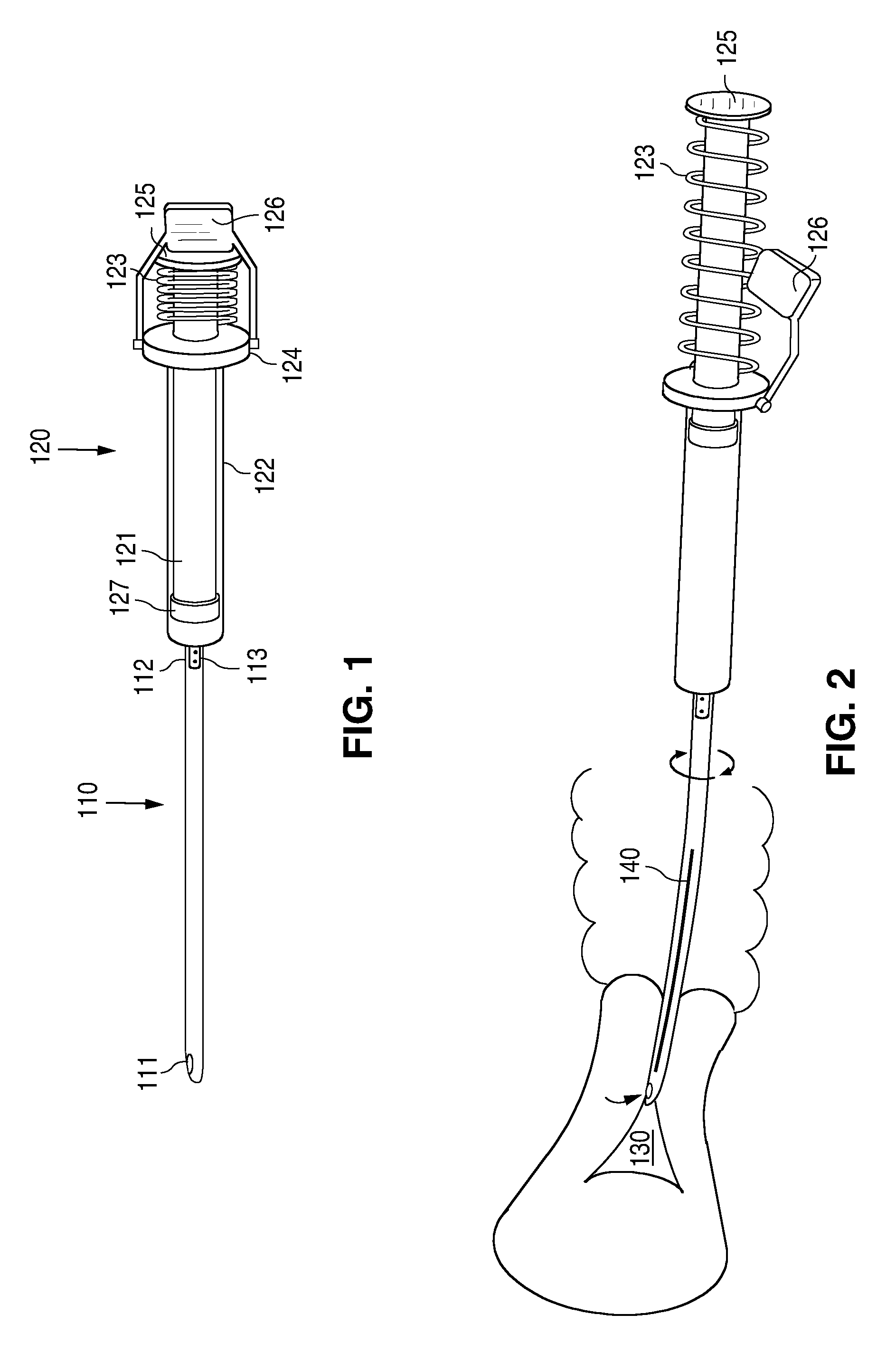
The present invention is an aspiration biopsy device that includes a catheter with a distally placed tissue acquisition side hole and a proximally attached syringe with a spring-loaded plunger and latching mechanism. The device can be manipulated to automatically create aspiration suction and collect biopsy samples from the body cavity. The method of using the device is simple, and the sample can be easily expelled by depressing the spring-loaded plunger with a thumb.

Problems solved by technology

However, the process of transferring the sample from the catheter to a specimen container is inherently difficult with such typical biopsy devices because the flexible plunger must be reintroduced into the flexible catheter to expel the contents.
This process is slow and technically difficult, and may result in loss of the sample, leading to the need for a second procedure.
Additionally, the limited volume of such typical endometrial catheters frequently does not create enough suction to obtain an adequate sample, and multiple passes with the same catheter, consisting of multiple iterations of obtaining and expelling a sample, must be performed.
This process is further complicated by the need to prevent the sterile catheter tip from touching a non-sterile specimen container in order to prevent contamination when multiple passes are required.
Thus, although such prior-art devices can be simple to use and manufacture, each suffers from the disadvantages of a limited amount of suction and the need to force a long, flexible plunger back into the device in order to retrieve the specimen.
These disadvantages result in loss of time and increased patient discomfort because the catheter must be reintroduced multiple times to retrieve an adequate sample and because the difficulty of replacing the plunger to retrieve the sample frequently leads to loss of sample, thus requiring a second procedure.
This action of pulling on the syringe plunger at the same time the catheter is inserted into the uterine cavity is inherently dangerous and may cause inadvertent harm or uterine perforation as the catheter is being pushed forward toward the patient and as the syringe is being pulled backward.
U.S. Pat. No. 5,971,939 A. These devices have a variety of disadvantages based on the complicated grips, guides, and holders that encase the syringe and therefore introduce difficulty in retrieving the specimen if it is suctioned into the syringe.

Method used


Image

  • Biopsy device with automatic aspiration
  • Biopsy device with automatic aspiration
  • Biopsy device with automatic aspiration

Examples


Embodiment Construction

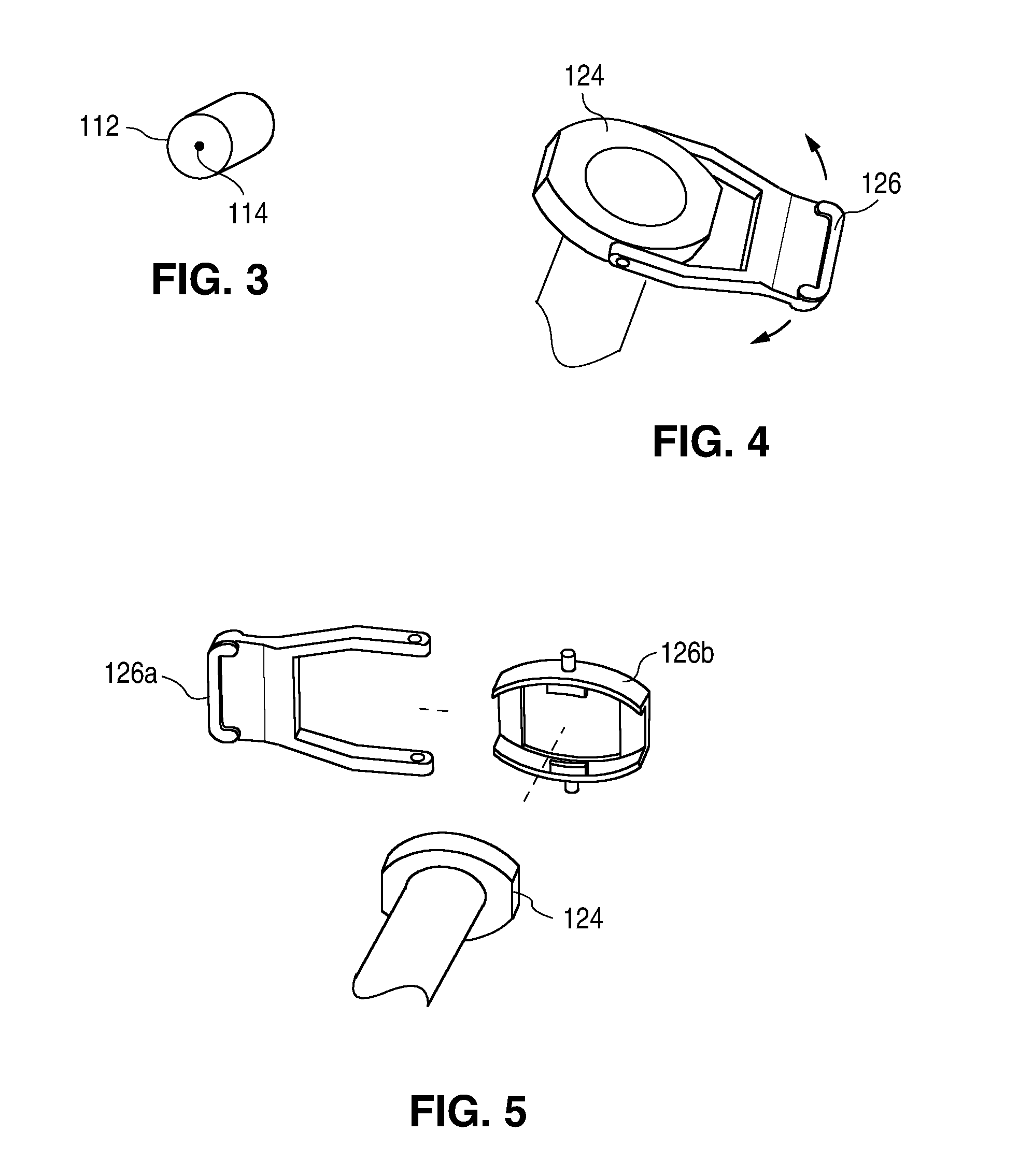
[0020]One aspect of the present invention is a biopsy device. In one embodiment, the device is an endometrial biopsy catheter with a proximally attached aspiration syringe, the catheter having a pin-hole channel or filter acting as a tissue trap to prevent aspiration of tissue from the catheter into the syringe. In another embodiment, the device is an aspiration biopsy device with a proximally attached syringe that has a spring-loaded plunger and a latching mechanism to automatically create aspiration suction when the latch is released. Devices in accordance with the present invention are illustrated in FIGS. 1-7.

[0021]FIG. 1 shows a biopsy device, in accordance with the present invention, ready for use. The device includes a catheter 110 (also referred to herein as an endometrial biopsy catheter) and a proximally attached syringe 120 (also referred to herein as an aspiration syringe). The term “catheter” is defined herein as an elongated, at least semi-flexible tube such as is illu...


PUM


Abstract

The invention provides a disposable endometrial biopsy device comprising an elongated blunt-end catheter with distally placed tissue acquisition side-hole and proximally attached aspiration syringe with spring-loaded plunger having latching mechanism to release plunger for induction of aspiration. The device has a pin-hole channel or filter acting as a tissue trap between the catheter channel and the syringe in order to prevent aspiration of tissue into the body of the syringe.

Description

CROSS REFERENCE TO RELATED APPLICATION[0001]This application claims the benefit of U.S. Provisional Application No. 61 / 717,745, filed Oct. 24, 2012, which is incorporated herein by reference in its entirety for all purposes.TECHNICAL FIELD[0002]This invention relates generally to surgical instruments. More particularly, the invention relates to a biopsy device that automatically creates suction to aspirate a specimen into the device.BACKGROUND OF THE INVENTION[0003]Routine endometrial biopsy is commonly performed using a flexible 3-mm catheter with rounded distal end having a side-hole for curettage and collection of tissue. Such catheters typically contain a flexible internal plunger that seals with the internal surface of the catheter. When the internal plunger is pulled back, suction is created. The suction is used to obtain endometrial tissue as the catheter is passed back and forth with rotation within the uterine cavity while the distal side hole scrapes tissue from the intern...

Claims


Application Information

Patent Timeline
IPC IPC(8): A61B10/02
CPCA61B10/0283A61B2010/0208
Inventor ZINNANTI, WILLIAM
Owner ZINNANTI WILLIAM
Learn More