Air conditioning apparatus

a technology of air conditioning apparatus and air conditioner, which is applied in the direction of indirect heat exchangers, lighting and heating apparatus, heating types, etc., can solve the problems of severe reduction of air-warming capability during defrosting, inability to defrost outdoor heat exchangers, and inability to increase integral air-warming capability

Inactive Publication Date: 2014-05-01
DAIKIN IND LTD
View PDF0 Cites 17 Cited by
  • Summary
  • Abstract
  • Description
  • Claims
  • Application Information

AI Technical Summary

Benefits of technology

[0012]In this air conditioning apparatus, because the refrigerant can be passed through to the subcooling path even during the air-warming defrost operation, drain water produced by defrosting the heat exchange path can be prevented from refreezing and can be quickly expelled from the bottom of the outdoor heat exchanger.

Problems solved by technology

However, in the defrosting system of Patent Literature 1, the frost (ice) does not melt when the temperature of the outdoor air is 0° C. or less, and the system therefore has a problem in that the outdoor heat exchanger cannot be defrosted in weather conditions of an outside air temperature of 0° C. or less in which a large air-warming load is required.
Defrosting requires time to melt frost using outdoor air having a small difference in temperature with the frost, and as a result, only a short time is needed to perform only the air-warming operation, and the system has a problem in that the integral air-warming capability cannot be increased.
In the defrosting system in Patent Literature 2, because some of the refrigerant sent to the indoor heat exchanger and used in air warming is used to defrost the outdoor heat exchanger, the system has a problem in that the air-warming capability during defrosting is severely reduced.

Method used


Image

  • Air conditioning apparatus
  • Air conditioning apparatus
  • Air conditioning apparatus

Examples


first embodiment

Overall Configuration

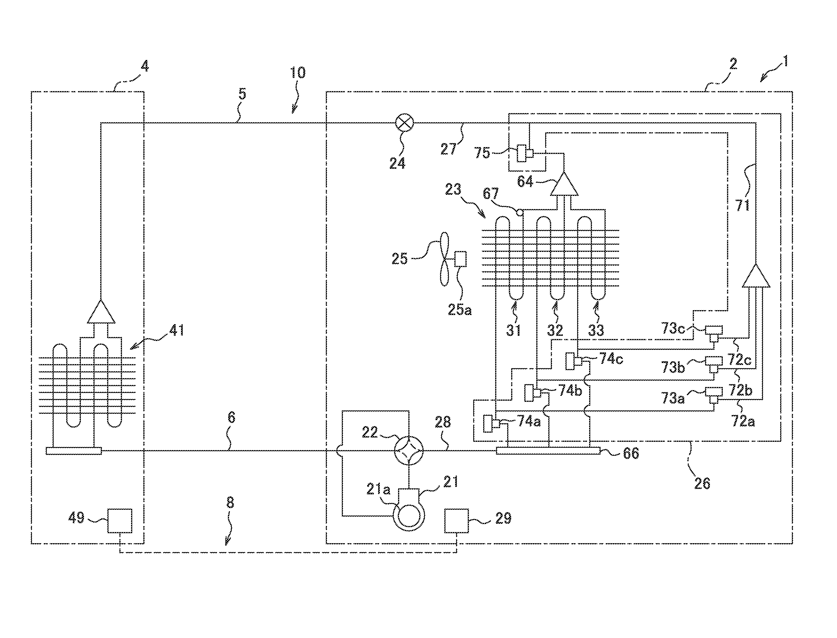
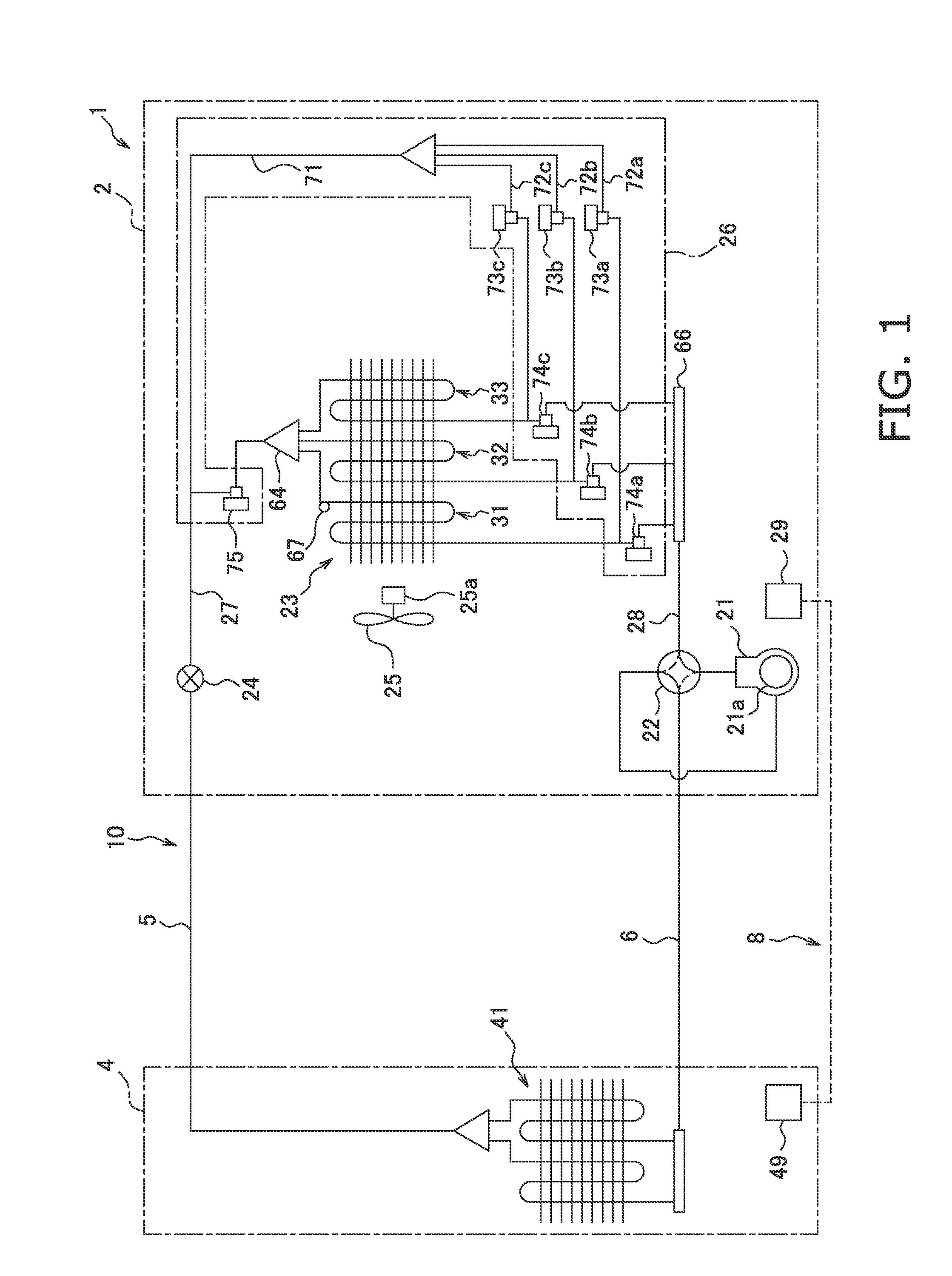
[0052]FIG. 1 is a schematic configuration diagram of the air conditioning apparatus 1 according to the first embodiment of the present invention. The air conditioning apparatus 1 is capable of performing an air-warming operation, and a split type apparatus is employed herein. The air conditioning apparatus 1 has primarily an outdoor unit 2, an indoor unit 4, and a liquid refrigerant communication tube 5 and a gas refrigerant communication tube 6 connecting the outdoor unit 2 and the indoor unit 4. By being connected via the liquid refrigerant communication tube 5 and the gas refrigerant communication tube 6, the outdoor unit 2 and the indoor unit 4 constitute a refrigerant circuit 10 for performing a vapor compression type refrigeration cycle.

[0053](Indoor Unit)

[0054]The indoor unit 4, which is installed indoors, constitutes part of the refrigerant circuit 10. The indoor unit 4 has primarily an indoor heat exchanger 41.

[0055]The indoor heat exchanger 41 is a hea...

second embodiment

[0138]In the above embodiment and the modifications thereof, the configuration of the air-warming defrost operation according to the present invention was applied to an outdoor heat exchanger 23 having a plurality of heat exchange paths 31 to 33 connected to each other in parallel, but such a configuration is not provided by way of limitation to the present invention. The configuration of the air-warming defrost operation according to the present invention may be applied herein to an outdoor heat exchanger 123 having not only the plurality′ of heat exchange paths 31 to 33, but also a subcooling path 34 through which refrigerant passes before flowing into the refrigerant flow diverter 64

[0139]FIG. 21 is a schematic configuration diagram of the air conditioning apparatus 101 according to the second embodiment of the present invention. The air conditioning apparatus 101 has primarily an outdoor unit 102, an indoor unit 4, and a liquid refrigerant communication tube 5 and a gas refriger...


PUM


Abstract

An air conditioning apparatus includes a defrosting flow channel mechanism. The air conditioning apparatus performs an air-warming defrost operation in which refrigerant sent from an indoor heat exchanger to an outdoor heat exchanger is evaporated while defrosting an arbitrarily selected heat exchange path using the defrosting flow channel mechanism. In the defrost operation, the refrigerant sent to the outdoor heat exchanger from the indoor heat exchanger is not channeled into the refrigerant flow diverter but is passed through the arbitrarily selected heat exchange path from the gas-side end to the liquid-side end of the arbitrarily selected heat exchange path, and the refrigerant passed through the arbitrarily selected heat exchange path flows through the refrigerant flow diverter to be passed through other heat exchange paths other than the arbitrarily selected heat exchange path from the liquid-side end to the gas-side end of the other heat exchange paths.

Description

TECHNICAL FIELD[0001]The present invention relates to an air conditioning apparatus, and particularly relates to an air conditioning apparatus capable of performing an air-warming operation.BACKGROUND ART[0002]In the past there have been air conditioning apparatuses configured by sequentially connecting a compressor, an indoor heat exchanger, and an outdoor heat exchanger, and capable of performing an air-warming operation of circulating refrigerant in order through the compressor, the indoor heat exchanger, the outdoor heat exchanger, and the compressor. When frost forms on the outdoor heat exchanger in such an air conditioning apparatus, a reverse cycle defrosting operation is performed in which a switch is made by a four-way switching valve or the like so that the refrigerant is circulated in order through the compressor, the outdoor heat exchanger, the indoor heat exchanger, and the compressor to defrost the outdoor heat exchanger. Therefore, in this air conditioning apparatus, ...

Claims


Application Information

Patent Timeline
Patent Type & Authority Applications(United States)
IPC IPC(8): F25B29/00
CPCF24F2011/0089F25B47/02F24F11/02F25B13/00F25B29/003F25B41/04F24F1/14F24F1/30F25B2347/021F25B39/028F25B47/022F25B2313/0233F25B2313/0251F25B2313/0253F25B2313/02741F28F9/0275F28D1/0443F28D1/0477F24F11/42F24F11/89
Inventor DOUMYOU, NOBUOKURIHARA, TOSHIYUKIMORIMOTO, KOUSUKE
Owner DAIKIN IND LTD
Why Eureka
Try Eureka