Lighting device

Active Publication Date: 2014-05-01
LEXTAR ELECTRONICS CORP
View PDF6 Cites 4 Cited by
  • Summary
  • Abstract
  • Description
  • Claims
  • Application Information

AI Technical Summary

Benefits of technology

[0022]According to the present disclosure, the reflective plate and light bar of the lighting device are kept distant by a distance (H), and while the light bar outputted the light, the area of the light projected on the reflective plate is smaller than the overall area of the output surface of the lighting device. In this way, while disposing the wavelength-converting materials on the reflective plate, the usage of wavelength-converting materials could be reduced, as compared with conventional coating techniques; also, the wavelength conversio

Problems solved by technology

As the phosphors are quite costly, the manufactu

Method used


Image

  • Lighting device
  • Lighting device
  • Lighting device

Examples


Example

[0028]In the following detailed description, for purposes of explanation, numerous specific details are set forth in order to attain a thorough understanding of the disclosed embodiments. In accordance with common practice, the various described features / elements are not drawn to scale but instead are drawn to best illustrate specific features / elements relevant to the present invention. Also, like reference numerals and designations in the various drawings are used to indicate like elements / parts. Moreover, well-known structures and devices are schematically shown in order to simplify the drawing and to avoid unnecessary limitation to the claimed invention.

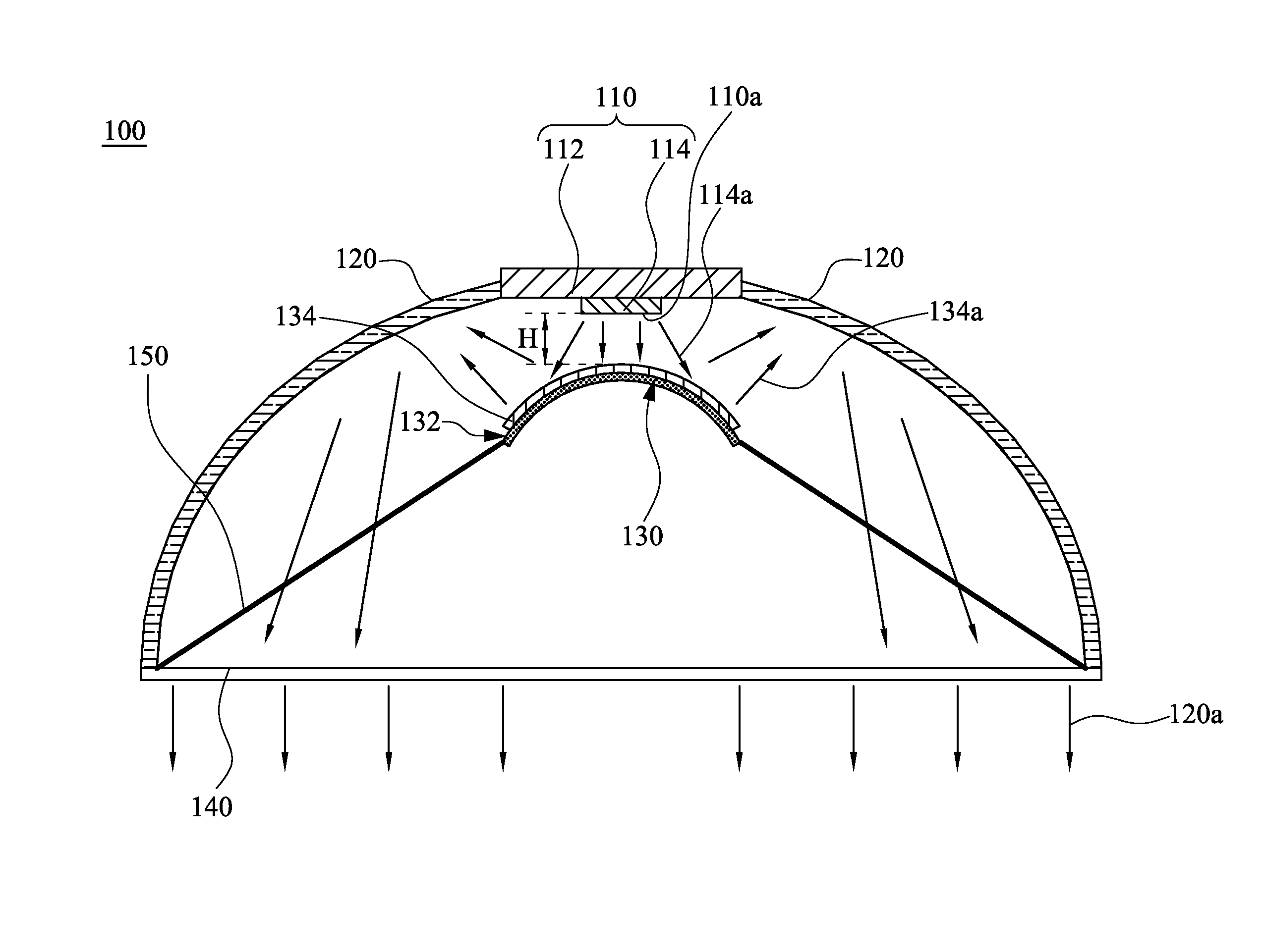
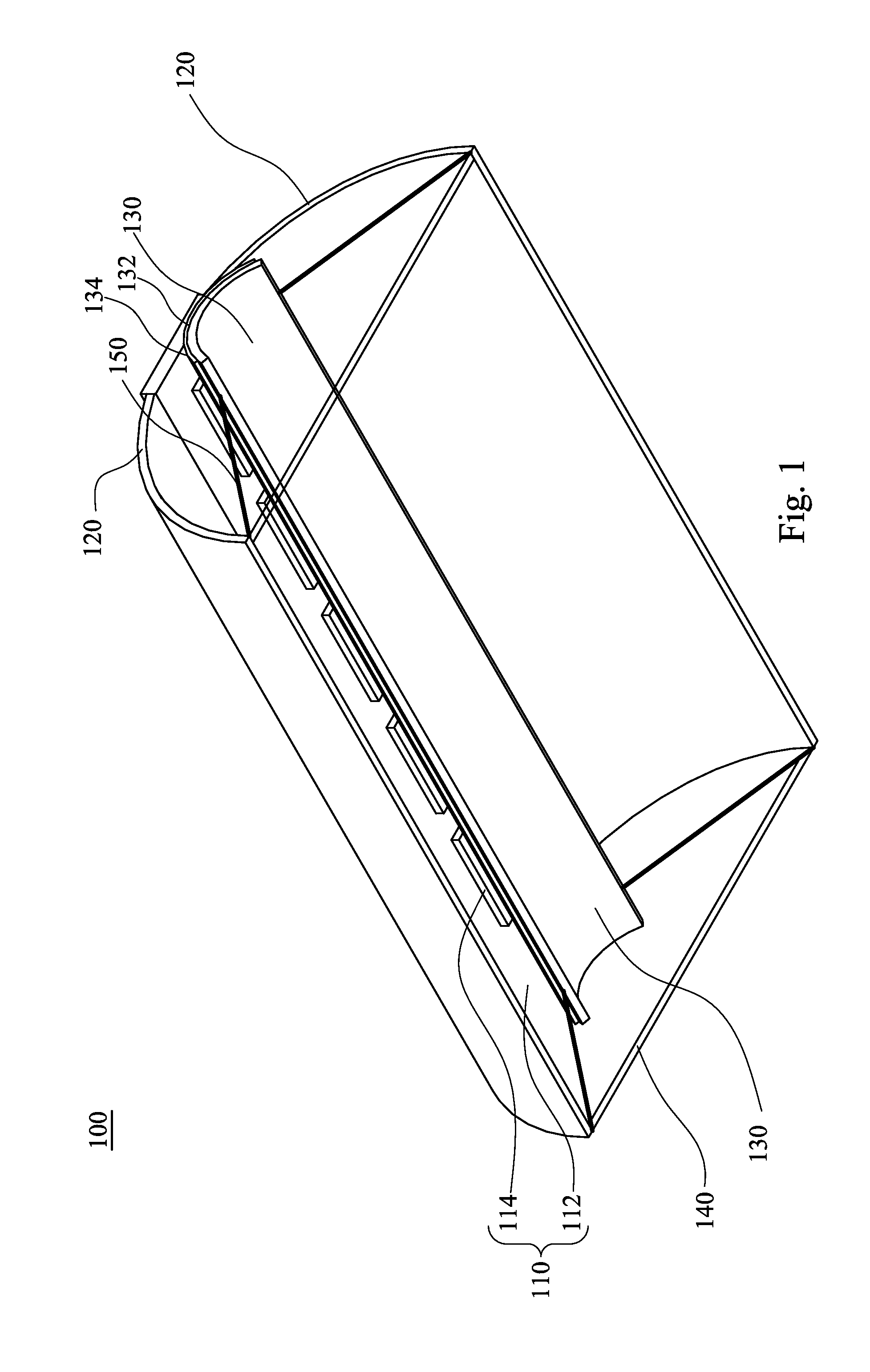
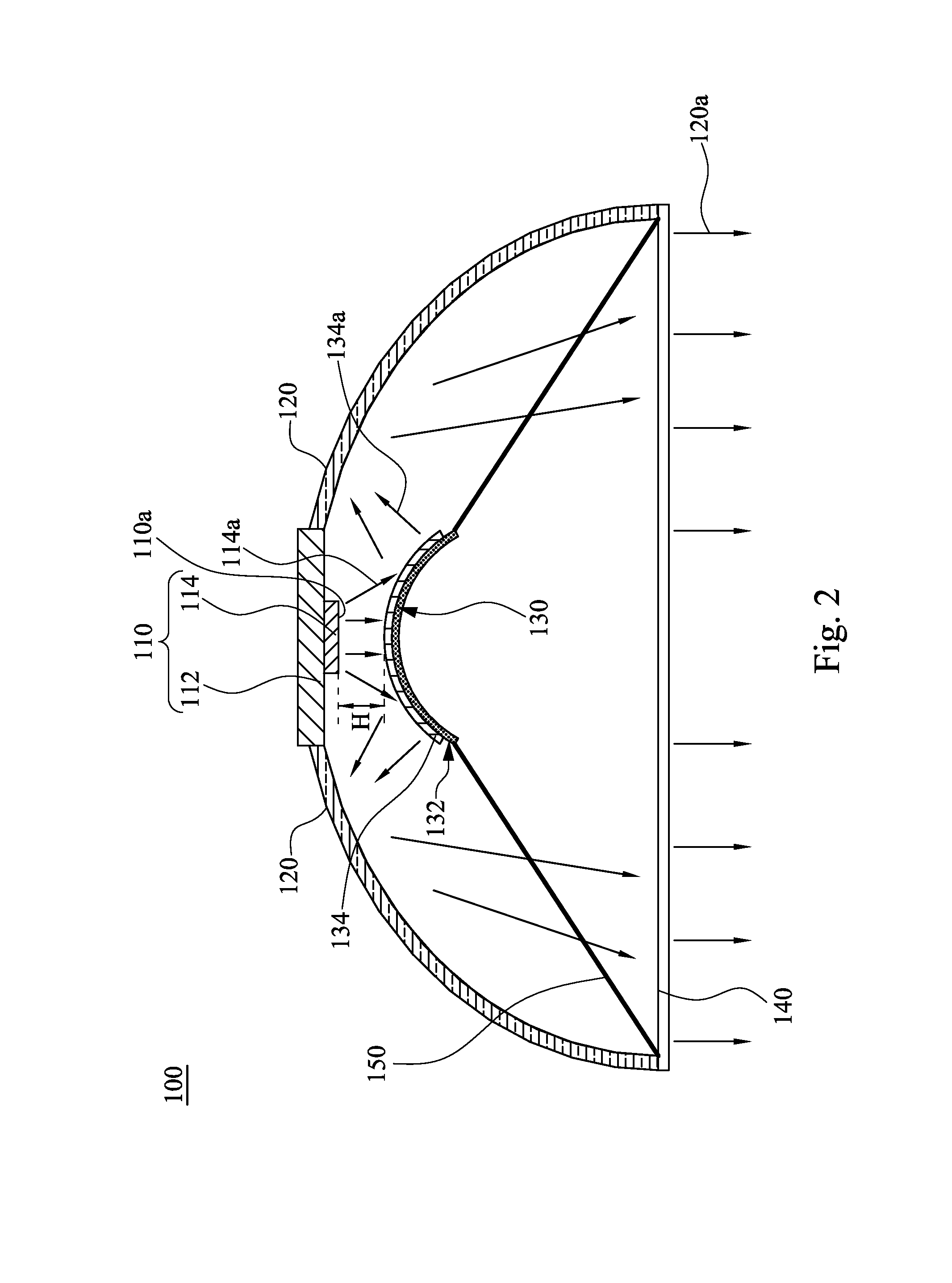
[0029]Please refer to FIGS. 1 and 2, in which FIG. 1 is pictorial drawing illustrating a lighting device 100 according to one embodiment of the present disclosure; while FIG. 2 is a main view drawing illustrating the lighting device 100 according FIG. 1.

[0030]In the present embodiment, the lighting device 100 comprises a light bar...


PUM


Abstract

A lighting device includes a light bar, two reflective covers and a reflective plate. The two reflective covers respectively connected to two opposite long sides of the light bar. The reflective plate is positioned at the light output side of the light bar. The reflective surface of the reflective plate faces the light output side of the light bar. The reflective plate has a wavelength conversion layer positioned on the reflective surface thereof. The light bar emits a first wavelength light, and a portion of the first wavelength light is converted by the wavelength conversion layer into a second wavelength light which is reflected by the reflective plate to the two reflective covers, while the remaining non-converted first wavelength light is reflected by the reflective plate to the two reflective covers and mixed with the second wavelength lights to give a light with a predetermined spectrum.

Description

RELATED APPLICATIONS[0001]This application claims priority to Taiwan Patent Application No. 101139488, filed Oct. 25, 2012, the entirety of which is herein incorporated by reference.BACKGROUND[0002]1. Technical Field[0003]The present disclosure relates to a lighting device; more particularly, a lighting device for emitting twice-reflected light.[0004]2. Description of Related Art[0005]Recently, as the energy crisis attracts more and more attention, various innovative energy-saving lighting devices have been developed. Among them, the light-emitting diode (LED) is believed to be the next-generation lighting tool because of its advantageous characteristics of high luminescent efficiency, low power consumption, and mercury-free and long service life.[0006]Regarding white light LED for illuminating purposes, the conventional technology has disclosed various manufacturing processes. Among them, some processes utilize the LED chip together with phosphors; for example, the blue light emitt...

Claims


Application Information

Patent Timeline
IPC IPC(8): F21V13/08F21V13/12
CPCF21V13/08F21V13/12F21K9/62F21K9/64F21V13/14F21Y2115/10
Inventor LIN, CHING-YAO
Owner LEXTAR ELECTRONICS CORP
Why Eureka
Try Eureka