Asynchronous serial data interface

Inactive Publication Date: 2010-11-02
RPX CORP
View PDF12 Cites 5 Cited by
  • Summary
  • Abstract
  • Description
  • Claims
  • Application Information

AI Technical Summary

Benefits of technology

[0037]Compared to the software protocol with “Escape Sequences” the invention reduces the processor usage considerably which would ot

Problems solved by technology

If this instance is handled by a microprocessor (software flow control) which at some time, i.e. with some delay, discovers that the RTS/CTS is set to ‘flow off’ and then has to stop the UART from continuing transmission the delay may be in the range of multiple bytes, and in the worst case the exact delay is not predictable.
A difficult situation arises when there is no hardware support for flow control.
Bytes can get lost if the software in the receiver and the transmitter does not react fast enough to prevent buffer overflow.
In this case packet s

Method used


Image

  • Asynchronous serial data interface
  • Asynchronous serial data interface
  • Asynchronous serial data interface

Examples


embodiment

PREFERRED EMBODIMENT

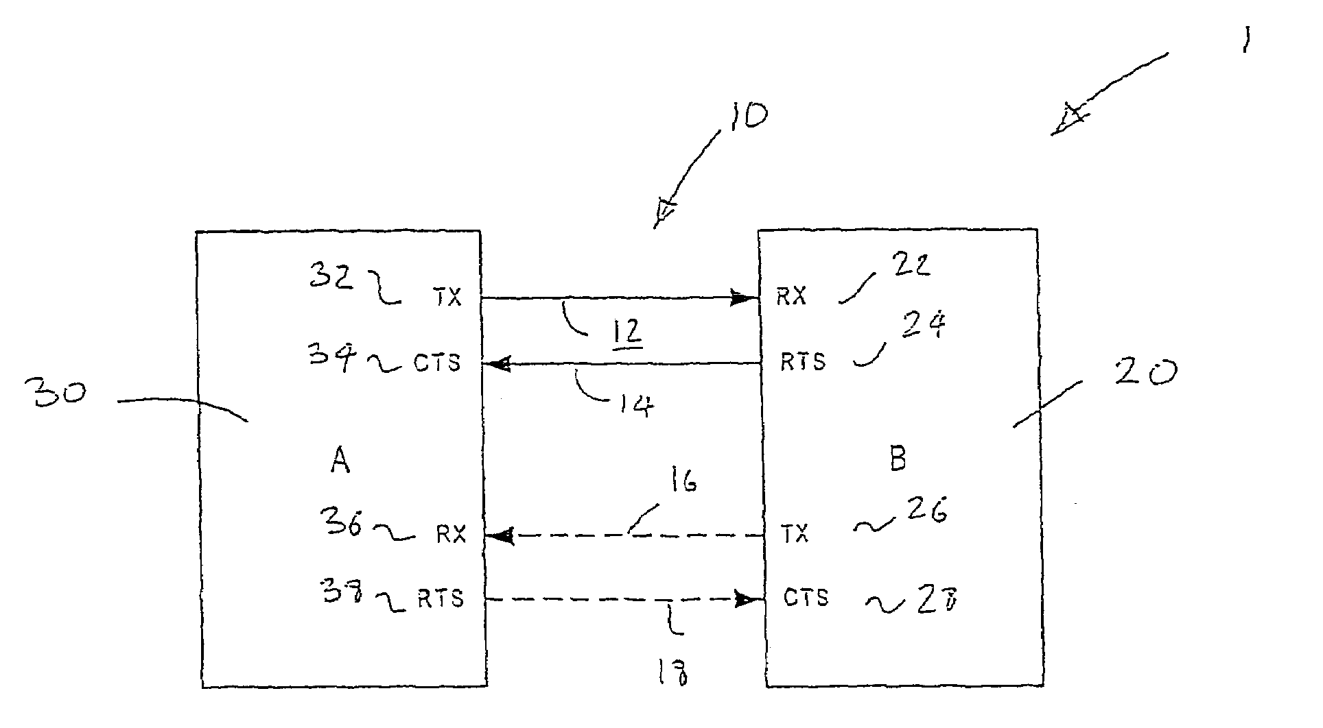
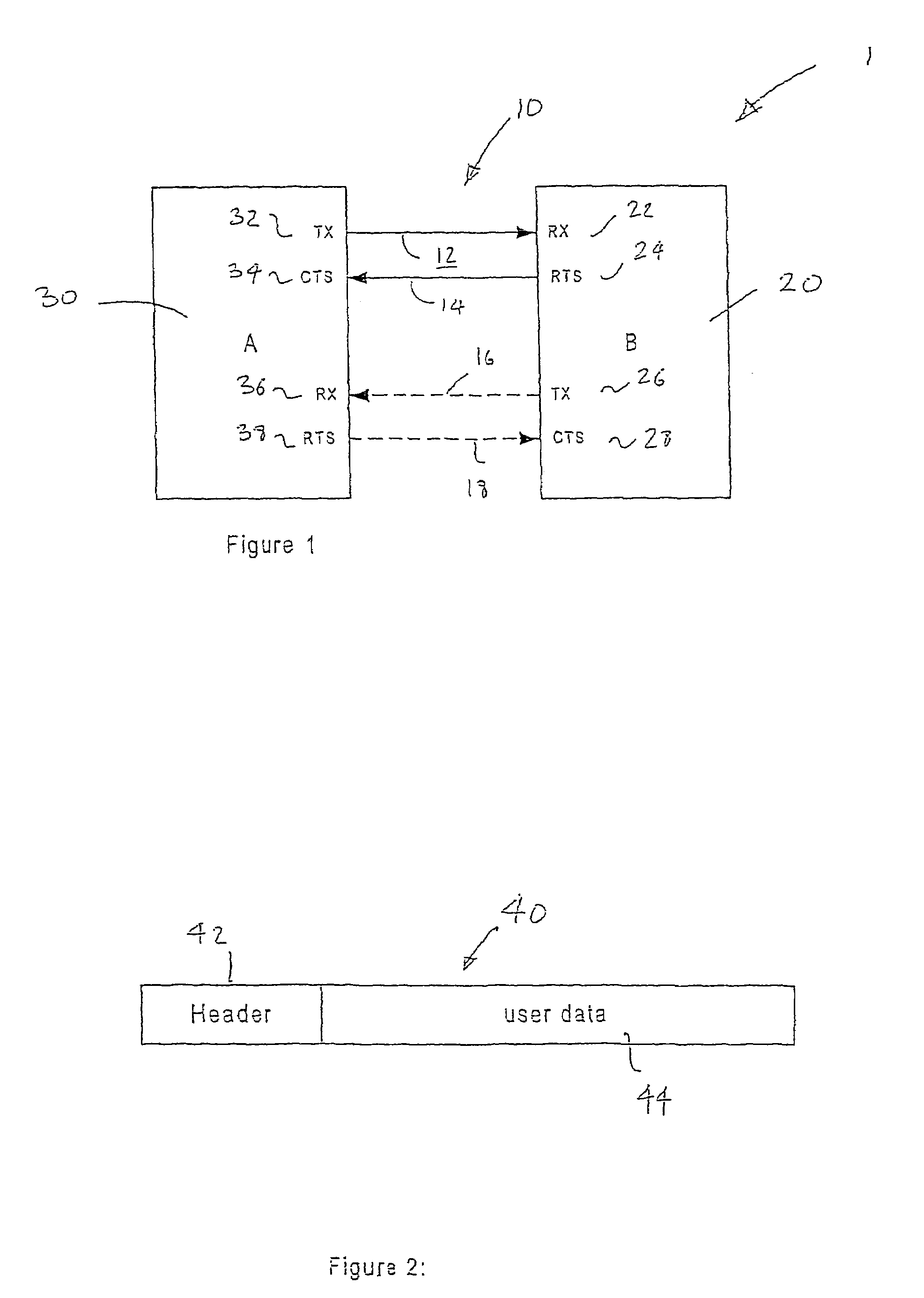
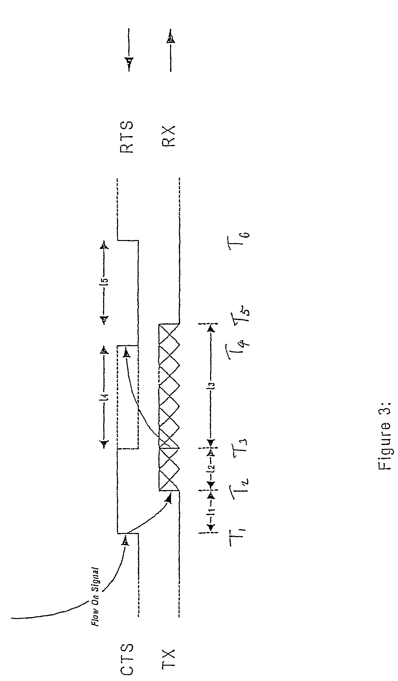
[0055]The flow control between transmitter and receiver is handled packet wise. The detection of the rising edge of RTS / CTS allows the transmission of only one packet. The receiver de-asserts the RTS / CTS inactive once the packet header has been received. The transmitter is not allowed to transmit the next packet until detection of another rising edge of the RTS / CTS signal. The flow control handling is illustrated in FIG. 3. When the RTS / CTS goes inactive the transmitter completes transmission of the current packet. When RTS / CTS goes from inactive to active this signals the transmission of the next single packet.

[0056]Referring to FIG. 3, RTS / CTS goes active at time T1. There is a latency t1 for detection of the rising edge at the transmitter. The transmitter detects the rising edge at T2. The transmitter takes t2 to transmit the packet header and starts transmitting the rest of the packet at T3 which takes t3. The transmitter finishes transmitting the packet at T...

embodiment 2

[0078]When the RTS / CTS goes low the transmitter completes transmission of the current packet. When RTS / CTS goes from inactive to active this signals the transmission of the next packet.

[0079]The receiver monitors the remaining memory and an alert is created when the remaining memory falls below some threshold and is reset when the available memory rises above the threshold. The receiver puts RTS / CTS inactive only when there is an alert AND after a packet header has been received. That is, instead of changing RTS / CTS from active to inactive after every packet header is received as in the preferred embodiment, the transition only occurs when there is a risk of overflow. The transmitter would continuously send packet after packet while RTS / CTS remains active, and restarts continuously sending packet after packet when CTS / RTS goes inactive-active (i.e. inactive-active transition says ‘restart data stream’ as opposed to ‘send one packet’).

[0080]The receiver does the following:[0081]1. de...


PUM


Abstract

A receiver for receiving packet data from a transmitter, the transmitter and the method of controlling transmission. The receiver may comprise first detection means for detecting that its memory has enough space to store a data packet and flow control signal means for providing a flow control signal, preferably a first flow control signal, to the transmitter in response to said first detection means. The receiver may comprise second detection means for detecting when a first portion of a packet has been received from the transmitter and flow control signal means for providing a second flow control signal to the transmitter in response to said second detection means. The transmitter may comprise third detection means for detecting the second flow control signal sent by the receiver and packetwise transmission means arranged, responsive to the third detection means, to complete transmission of a partially transmitted packet and then to stop transmission of further packets.

Description

FIELD OF THE INVENTION[0001]This invention relates to a serial communication system with data flow on a cable, e.g. a Universal Asynchronous Receiver / Transmitter (UART). The data is packet data.BACKGROUND OF THE INVENTION[0002]A UART has a data connector connecting a transmitter to a receiver. The data sent from the transmitter to the receiver may be packet data. A packet is made up of multiple bytes of data. When the transmitter is sending packets asynchronously to the receiver it is important for the receiver to know where one packet ends and the next packet begins.[0003]It is known for the receiver to count received bits / bytes from the start of communication. The first data bytes the receiver receives then must be the start of a packet. The receiver knows length information about the packet, and from this information the receiver can calculate when the end of the packet is received. Consequently, the next bytes it receives must be the start of the next packet. Thus the transmitte...

Claims


Application Information

Patent Timeline
IPC IPC(8): H04L27/00G06F13/38H04L12/811H04L29/10
CPCG06F13/385G06F13/38H04L47/38H04L69/32
Inventor SCHNEIDER, GREGORBENCAK, DANIEL
Owner RPX CORP
Why Eureka
Try Eureka