Optical demultiplexer circuit and demultiplexer device and optical wavelength division multiplex circuit

Inactive Publication Date: 2005-04-07
FUJITSU OF KAWASAKI
View PDF6 Cites 7 Cited by
  • Summary
  • Abstract
  • Description
  • Claims
  • Application Information

AI Technical Summary

Benefits of technology

[0014] It is an object of the present invention to provide a demultiplexer device for demultiplex syst

Problems solved by technology

As transmission signal speeds of wavelength division multiplexing systems increase, the penalty rate increases for the self-phase modulation caused by the group velocity dispersion (GVD) of the optical fiber that is the transmission path.
However, because the dispersion characteristics of the transmission path are dependent upon wavelength, when the wavelength division

Method used


Image

  • Optical demultiplexer circuit and demultiplexer device and optical wavelength division multiplex circuit
  • Optical demultiplexer circuit and demultiplexer device and optical wavelength division multiplex circuit
  • Optical demultiplexer circuit and demultiplexer device and optical wavelength division multiplex circuit

Examples


Example

[0042] Reference will now be made in detail to the preferred embodiments of the present invention, examples of which are illustrated in the accompanying drawings, wherein like reference numerals refer to like elements throughout.

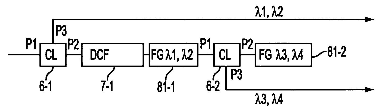
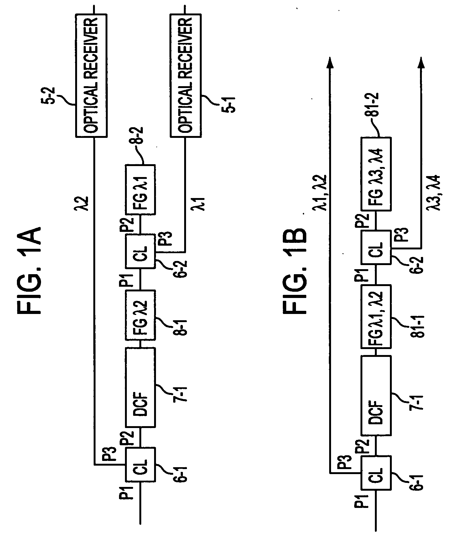
[0043]FIGS. 1A and 1B respectively illustrate optical demultiplexer devices in accordance with embodiments of the present invention. As shown in FIGS. 1A and 1B, the optical demultiplexer devices include optical circulators 6-1 and 6-2, a dispersion compensator 7-1, and fiber grating filters 8-1, 8-2, 81-1, 81-2. As shown in FIG. 1A, optical receivers 5-1 and 5-2 receive light corresponding to the respective wavelengths of light λ1 and λ2, which are different wavelengths.

[0044] In operation of the optical demultiplexer device shown in FIG. 1A, first, light in which wavelength λ1 and wavelength λ2 have been wavelength division multiplexed is input at a first port P1 of a first optical circulator 6-1. The light input at the first port P1 of the first optical...


PUM


Abstract

An optical demultiplexer to reduce the number of expensive dispersion compensators when compensating secondary dispersion during demultiplexing. By providing optical circulators, dispersion compensators, and optical filters that reflect specified wavelengths and transmit wavelengths other than the specified wavelengths from among the outputs of the dispersion compensators, and causing specified wavelengths to make round trips of the dispersion compensators, the dispersion volume of the dispersion compensators is reduced.

Description

CROSS-REFERENCE TO RELATED APPLICATIONS [0001] This application is based upon and claims priority of Japanese Patent Application No. 11-041494, filed Feb. 19, 1999, the contents being incorporated herein by reference. BACKGROUND OF THE INVENTION [0002] 1. Field of the Invention [0003] The present invention relates to an optical transmission system employing an optical wavelength division demultiplexing system and, more particularly, the present invention relates to an optical demultiplexer device which performs demultiplexing using a reduced number of dispersion compensators. [0004] 2. Description of the Related Art [0005] Recently, the number of multiplexed wavelengths in an optical wavelength division multiplexing system has increased, from thirty-two (32) wavelengths, to sixty-four (64) wavelengths, to one-hundred twenty-eight (128) wavelengths. Furthermore, transmission signal speeds have increased from 2.5 Gb / s, to 5 Gb / s, to 100 Gb / s, and capacity has increased. [0006] As tran...

Claims


Application Information

Patent Timeline
IPC IPC(8): H04B10/2507G02B6/293G02B6/34H04B10/2519H04B10/2525H04B10/255H04B10/27H04B10/29H04J14/02
CPCG02B6/29317H04J14/02G02B6/29394
Inventor TOMITA, TAKAHARU
Owner FUJITSU OF KAWASAKI
Why Eureka
Try Eureka