Device combing fuel control valve and carbon canister, or fuel tank

Inactive Publication Date: 2006-11-30
SENTEC E&E CO LTD
View PDF11 Cites 6 Cited by
  • Summary
  • Abstract
  • Description
  • Claims
  • Application Information

AI Technical Summary

Benefits of technology

[0005] Accordingly, the primary object of the present invention is to provide a device combing a fuel control valve and a carbon canister, wherein when a car is tilted, the fuel gas or fuel liquid will prevent from draining out. When fuel in the fuel tank overflows, it will be resisted from draining out. The fuel control valve is assembled with the carbon canister so that the soft tubes used is reduced to reduce the manufacturing and assembled cost. Thereby the hollow can with cutting fuel as fuel drains

Problems solved by technology

Thereby the fuel gas cannot vent to outside without polluting air.
Thereby fuel gas cannot be reused smoothly.
Furthermore, conventional fuel control valve,

Method used


Image

  • Device combing fuel control valve and carbon canister, or fuel tank
  • Device combing fuel control valve and carbon canister, or fuel tank
  • Device combing fuel control valve and carbon canister, or fuel tank

Examples


Example

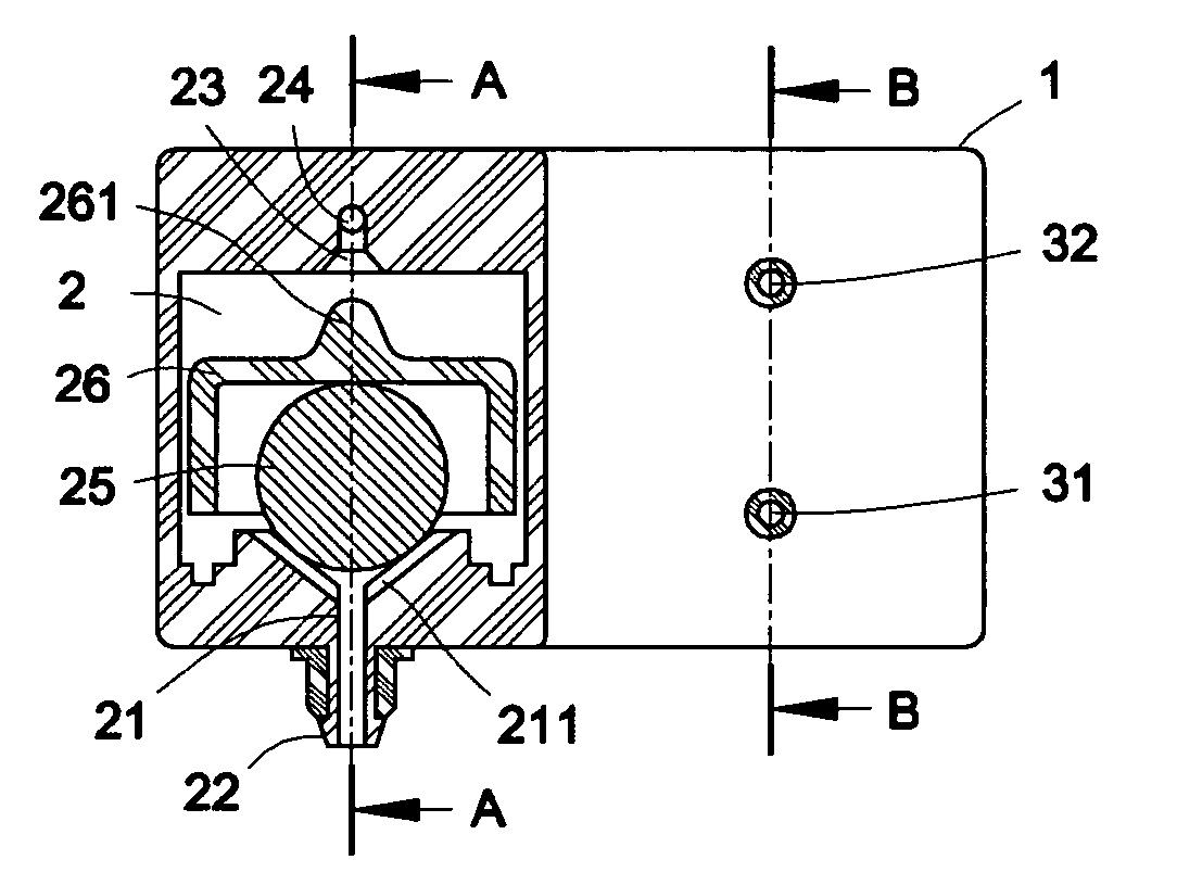
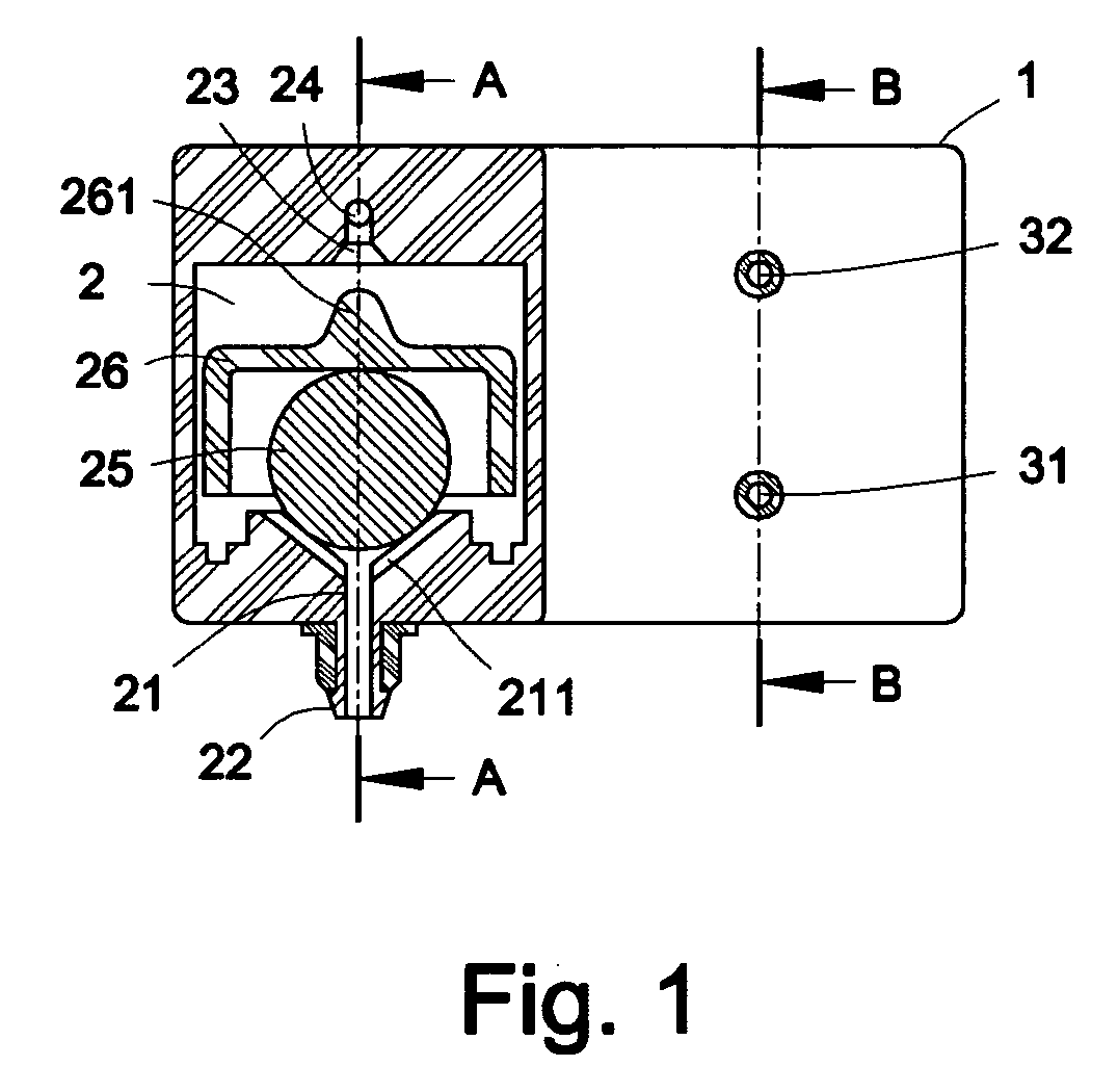
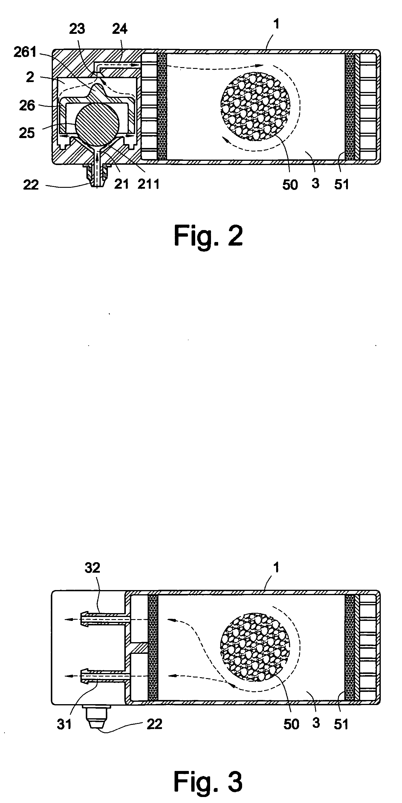
[0020] Referring to FIGS. 1 to 3, the arrangement of the first embodiment of the present invention is illustrated. A transversal hollow can 1 is installed with a first chamber 2 and a second chamber 3 which are spaced at two sides of the hollow can 1.

[0021] An interior of the first chamber 2 is installed with a vertical tapered tank 21 and a concave main valve gate 23 (referring to FIGS. 1 and 2). An interior of the tapered tank 21 is formed with a trench 211. A bottom of the tapered tank 21 is installed with a protruded and vertical gas tube 22 which is communicated to a fuel tank 4 (referring to FIG. 4). The main valve gate 23 is installed with a gas channel 24 which is communicated to the second chamber 3. An interior of the first chamber 2 is installed with a rolling element 25 and a floatable plug element 26. The rolling element 25 is for example a steel ball which is received in the tapered tank 21 and rolls freely. The floatable plug element 26 may be for example a U shape c...

Example

[0025] In the second embodiment of the present invention (referring to FIG. 4), the transversal hollow can 1 is integrally formed with the fuel tank 4. A fuel filling opening 44 is formed on the fuel tank 4 so that fuel liquid 41 can be filled into the fuel tank 4. A surface of the fuel liquid 41 in the fuel tank 4 is installed with an evaporation chamber 42. A top of a casing of the fuel tank 4 is formed with an assembled hole 43 which is communicated to the evaporation chamber 42. The gas tube 22 can be received in the assembled hole 43 so that the fuel gas in the fuel tank 4 can be guided into the first chamber 2 with lower resistance and the hollow can 1 ca be assembled at the top of the fuel tank 4. Thereby the assembled body according to the present invention is formed.

[0026] According to above mentioned structure, when fuel is supplied in a normal condition (referring to FIG. 4), the fuel gas inlet end of the engine has a negative pressure which will absorb the fuel gas in t...

Example

[0029] Besides referring to FIG. 7, the third embodiment of the present invention is illustrated. The difference of this embodiment from the above one is that the hollow can 1 is arranged vertically. The vertical hollow can 1 is formed with a first chamber 20 and a second chamber 30 which are spaced vertically. The first chamber 20 has a vertical channel 24 which is formed with a connecting tube 241. The first chamber 20 has a gas tube 220 which extends to a lateral side of the first chamber 20. Furthermore, a guide tube 33 is added to the second chamber 3s. A connecting tube 27 serves to connected the connecting tube 241 to the guide tube 22 so that fuel gas in the first chamber 20 will be guided to the second chamber 30. Other structure of this embodiment is identical to those above said embodiments and thus the details will not be described herein.


PUM


Abstract

A device combing a fuel control valve as fuel drains out and a carbon canister is disclosed. The device includes a hollow can and can be further combined with a fuel tank. The device has a first chamber for isolating draining fuel and a second chamber containing active carbon. The first chamber is formed with a gas tube which is connected to the fuel tank and a gas channel connected to the second chamber. The second chamber is formed with a gas return tube so as to form the device combing the fuel control valve and the carbon canister. The hollow can is assembled to a lateral wall of the fuel tank and the gas tube can be embedded into the fuel tank to form an integral structure.

Description

FIELD OF THE INVENTION [0001] The present invention relates to combination structures, and in particular to a device combing a fuel control valve and an active carbon or a fuel tank. BACKGROUND OF THE INVENTION [0002] In the prior art, to resolve the problem of evaporation of fuel gas in the fuel tank of a car, generally, a fuel gas return channel is added to the fuel tank. By the absorption force of the negative pressure at the gas inlet end of the engine, the fuel gas returns to the gas inlet end of an internal combustion engine to be used by the engine. Thereby the fuel gas cannot vent to outside without polluting air. [0003] In above mentioned gas return channel, a carbon canister (C / N) is arranged for absorbing evaporated fuel gas. To prevent the drainage of the fuel as the car is tilted, a fuel control valve is added to the gas return tube for closing the gas return tube immediately as the car falls down so that the fuel gas and the fuel will not drain out the atmosphere to po...

Claims


Application Information

Patent Timeline
IPC IPC(8): F02M33/02
CPCB60K15/03504F02M25/0836F02M37/0076F02M37/0023F02M25/0854
Inventor WANG, AARONHUANG, CHUN-CHAO
Owner SENTEC E&E CO LTD
Why Eureka
Try Eureka