
Method for dynamic load balancing of network flows on lag interfaces

a network flow and load balancing technology, applied in the field of dynamic load balancing of network flow on lag interfaces, can solve the problems of unbalanced load distribution across lag, data flow may not be uniformly distributed across all links, and not necessarily the case that throughput will scale linearly with port count, etc., to improve load sharing for link aggregation groups, improve load sharing, and improve load sharing.

Active Publication Date: 2014-05-01
TELEFON AB LM ERICSSON (PUBL)
View PDF10 Cites 127 Cited by
  • Summary
  • Abstract
  • Description
  • Claims
  • Application Information

AI Technical Summary

Benefits of technology

The patent describes a way for a network to balance its load by moving data flows to less busy ports. This is done by a network element that includes two line cards with ports, a switch fabric, and a processor. The processor uses congestion monitoring to identify overloaded ports and selects a new port for the data flow based on that information. The processor also updates a flow table to bind the data flow to the new port. The new port may be in the same link aggregation group as the original port, or in another group. The result is improved load sharing, reduced congestion, and better performance overall.

Problems solved by technology

The disadvantages of the prior art include that although link aggregation combines ports, it is not necessarily the case that throughput will scale linearly with port count.
Depending on the nature of the data traffic, the data flows may not be uniformly distributed across all the links in a link aggregation group.
The result is an unbalanced load distribution across the LAG causing sub-optimal performance due to some of the links in the LAG being congested while others are underutilized.
The drawback of the prior process is that the data flow distribution does not consider the utilization levels of the links in the LAG.
This uneven distribution causes the sub-optimal performance of the LAG, because data flows bound to congested links have lower throughput than would be possible if they were assigned to underutilized links of the LAG.
This causes an overall reduction in the efficiency and throughput of the LAG.

Method used


Image

  • Method for dynamic load balancing of network flows on lag interfaces
  • Method for dynamic load balancing of network flows on lag interfaces
  • Method for dynamic load balancing of network flows on lag interfaces

Examples


Embodiment Construction

[0012]In the following description, numerous specific details are set forth. However, it is understood that embodiments of the invention may be practiced without these specific details. In other instances, well-known circuits, structures and techniques have not been shown in detail in order not to obscure the understanding of this description. In other instances, control structures, gate level circuits and full software instruction sequences have not been shown in detail in order not to obscure the invention. Those of ordinary skill in the art, with the included descriptions, will be able to implement appropriate functionality without undue experimentation.

[0013]In the following description and claims, the terms “coupled” and “connected,” along with their derivatives, may be used. It should be understood that these terms are not intended as synonyms for each other. “Coupled” is used to indicate that two or more elements, which may or may not be in direct physical or electrical conta...


PUM


Abstract

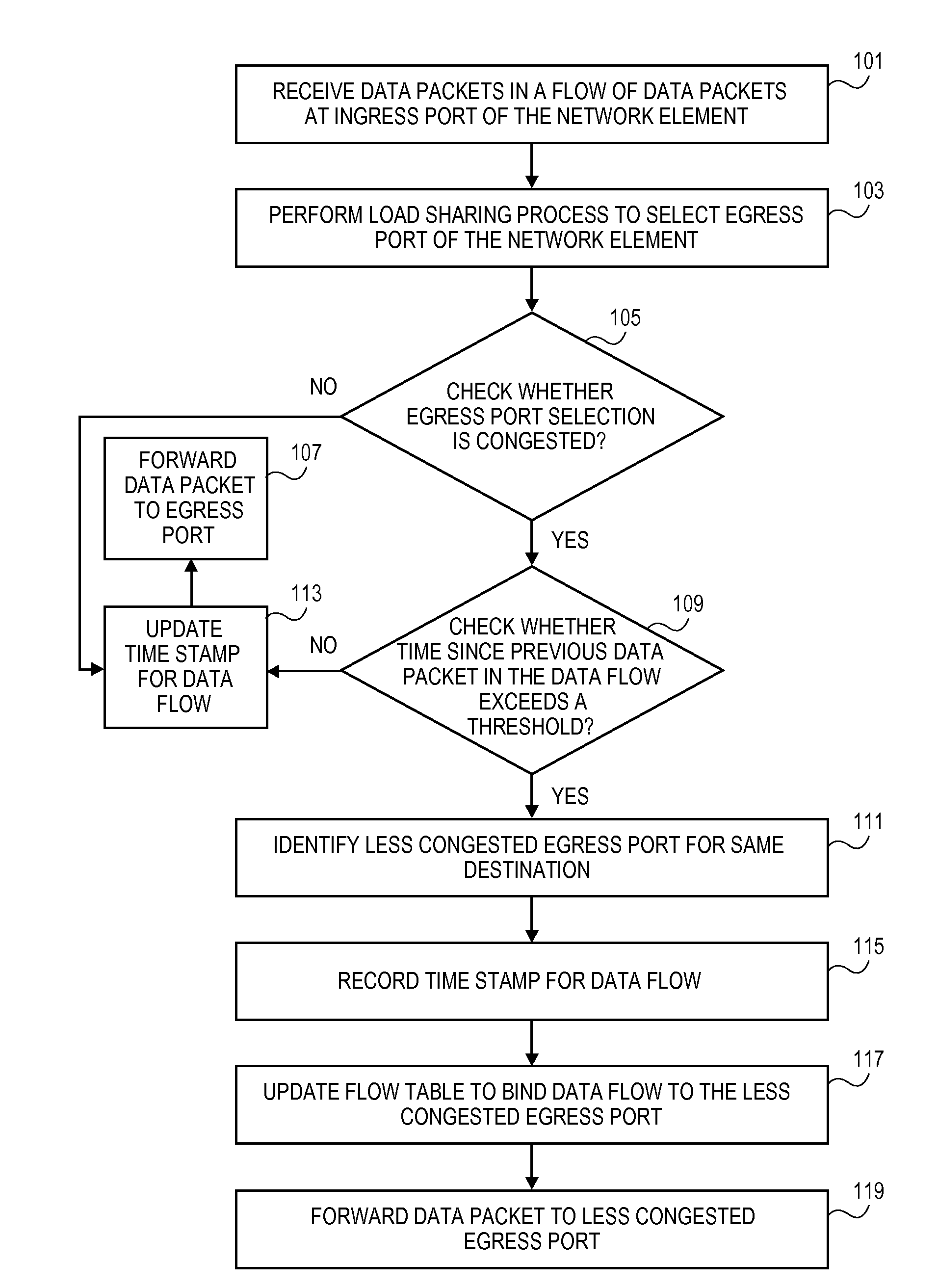
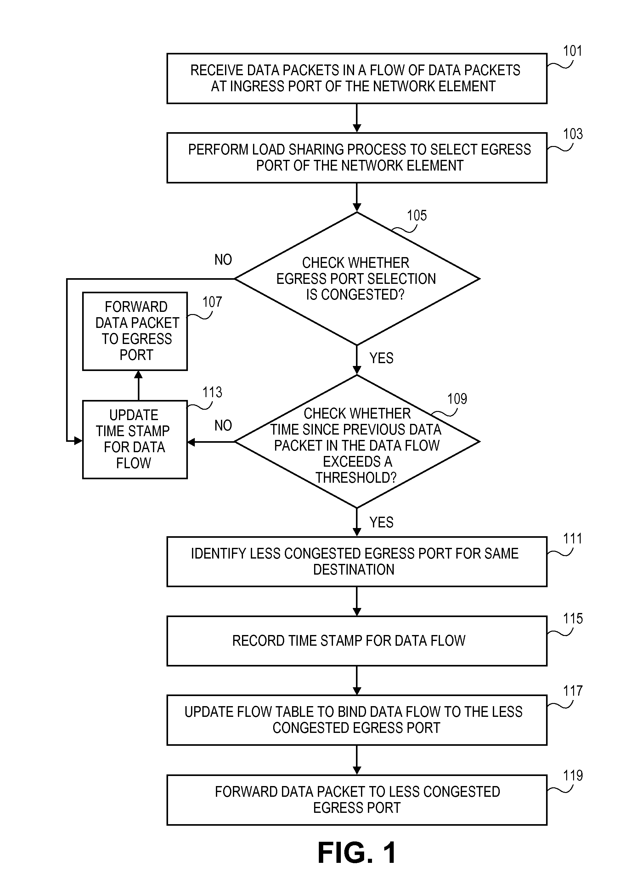
A method is implemented by a network element to improve load sharing for a link aggregation group by redistributing data flows to less congested ports in a set of ports associated with the link aggregation group. The network element receives a data packet in a data flow at an ingress port of the network element. A load sharing process is performed to select an egress port of the network element. A check is whether the selected egress port is congested. A check is made whether a time since a previous data packet in the data flow was received exceeds a threshold value. A less congested egress port is identified in the set of ports. A flow table is updated to bind the data flow to the less congested egress port and the data packet is forwarded to the less congested egress port.

Description

FIELD OF THE INVENTION[0001]The embodiments of the invention relate to a method and system for load balancing. Specifically, the embodiments relate to a method and system for redistributing data flows over a link aggregation interface to improve throughput.BACKGROUND[0002]Link aggregation is a term utilized in the field of computer networking to describe processes for using multiple network connections (i.e., links) in parallel (i.e., in an aggregated manner) to increase the throughput of a network element. Use of multiple network connections in place of a single connection provides a higher throughput than the single connection could sustain. The use of link aggregation also provides redundancy in case one of the links fails. The throughput may be diminished in the case of a single link failure, but the connectivity will not be lost because the other links continue to service the communication between a source and destination node where link aggregation is supported.[0003]Link aggr...

Claims


Application Information

Patent Timeline
IPC IPC(8): H04L12/24H04L45/24H04L45/243H04L45/28
CPCH04L45/245H04L45/22H04L45/28H04L47/125
Inventor ANAND, PRASHANTBALACHANDRAN, ARUN
Owner TELEFON AB LM ERICSSON (PUBL)
Learn More