Composite fiber guidewires

Active Publication Date: 2014-05-01
KONINKLIJKE PHILIPS ELECTRONICS NV
View PDF15 Cites 14 Cited by
  • Summary
  • Abstract
  • Description
  • Claims
  • Application Information

AI Technical Summary

Benefits of technology

[0045]In another embodiment the method further comprises the step of binding the fibers in the distal tip with a second matrix material for binding the fibers. The flexibility of the second matrix material is higher than the first matrix material. This embod

Problems solved by technology

A difficulty with integrating a sensor into a guidewire is that active guidewires would

Method used


Image

  • Composite fiber guidewires
  • Composite fiber guidewires
  • Composite fiber guidewires

Examples


Example

[0060]Like numbered elements in these figures are either equivalent elements or perform the same function. Elements which have been discussed previously will not necessarily be discussed in later figures if the function is equivalent.

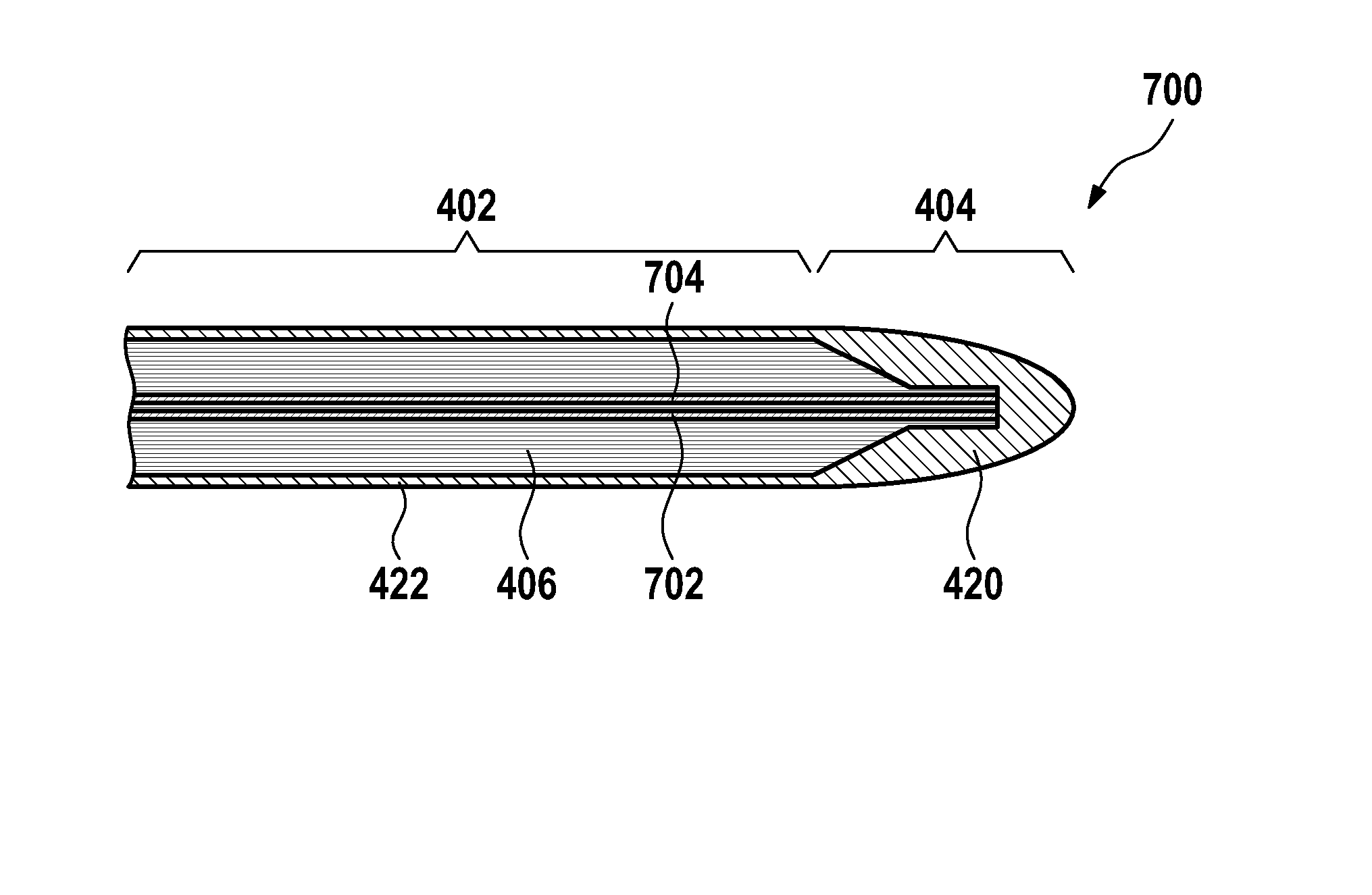
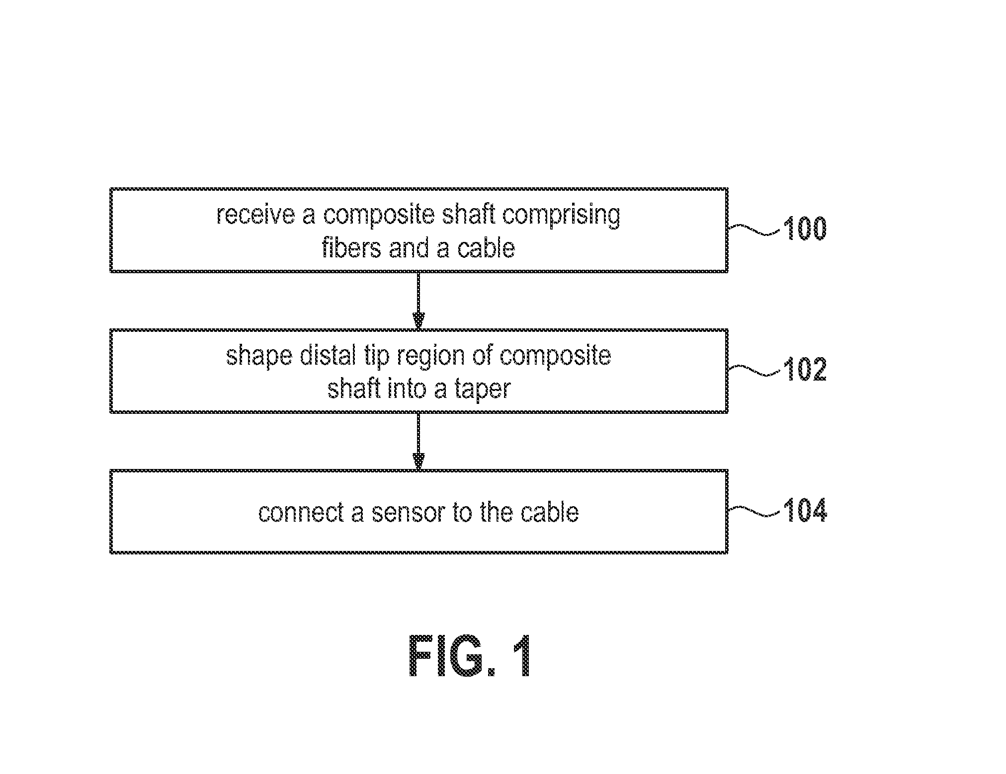
[0061]FIG. 1 shows a flowchart which illustrates a method according to an embodiment of the invention. In step 100 a composite shaft is received comprising fibers and a cable. For instance the cable may be formed into the fiber composite or it may be attached to an outside surface of the composite shaft. Next in step 102 a distal tip region of the composite shaft is shaped into a taper. Shaping the distal tip region into a taper allows the flexibility of the distal tip region to be increased. Finally in step 104 a sensor is connected to the cable.

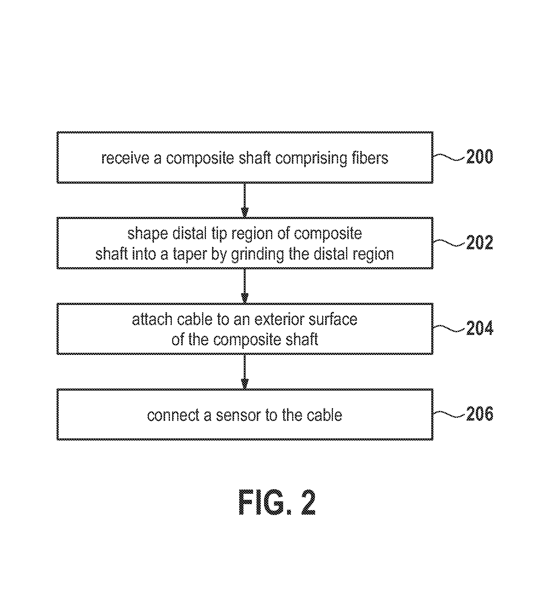
[0062]FIG. 2 shows a flow diagram which illustrates a method according to a further embodiment of the invention. In step 200 a composite shaft is received comprising fibers. Next in step 202 the distal tip regi...


PUM

PropertyMeasurementUnit
Lengthaaaaaaaaaa
Flexibilityaaaaaaaaaa

Abstract

A guide wire (400, 500, 600, 700, 800, 900, 1000, 1200, 1300) is adapted for use in magnetic resonance imaging systems. The guide wire has a shaft region (402) and a distal tip region (404). The shaft region comprises a composite shaft (406) comprising reinforcing fibers aligned with a length extension (403) of the shaft region. The fibers extend at least partially into the distal tip region. The fibers form a taper (410) within the distal tip region. The distal tip region comprises a sensor (504, 604, 702, 704, 804, 904, 1006, 1008). The shaft comprises a cable (502, 602, 702, 704, 802, 902, 1002, 1004). The cable is connected to the sensor.

Description

TECHNICAL FIELD [0001]The invention relates to guidewires for guiding a catheter or used stand-alone for in-body sensing, in particular to guidewires that are suitable to be guided using magnetic resonance imaging.BACKGROUND OF THE INVENTION [0002]Guidewires are mostly used to guide catheters. Standard guidewires used in interventional X-ray are passive devices made from conductive materials, mostly metals. They are easily visualized in X-ray projections and CT by their radio-opacity due to metal contents. Active guidewires are important as well in clinical practice. The use of active guidewires for measurement of pressure, temperature, and flow is common in interventional X-ray.[0003]In magnetic resonance imaging, a large magnetic field is used to align the nuclear spins of atoms as part of the procedure for producing images within the body of a subject. Magnetic resonance imaging is typically used to map the location of protons, such as those in a water molecule, within a subject....

Claims


Application Information

Patent Timeline
IPC IPC(8): A61M25/09B29C70/52
CPCA61M25/09B29C70/52A61B5/01A61B5/02154A61B5/055A61B5/11A61B5/6851A61B2562/12A61M2025/09108A61M2025/09133A61M2025/09175
Inventor WEISS, STEFFEN
Owner KONINKLIJKE PHILIPS ELECTRONICS NV
Why Eureka
Try Eureka