Rotary cutter apparatus and printer

a rotary cutter and printer technology, applied in the direction of printing, metal working apparatus, other printing apparatus, etc., can solve the problems of object to be cut erroneously advancing toward the rotary blade, and the means for guiding the object to be cut are not particularly provided, so as to achieve the effect of stably cutting

Active Publication Date: 2014-05-08
BROTHER KOGYO KK
View PDF6 Cites 12 Cited by
  • Summary
  • Abstract
  • Description
  • Claims
  • Application Information

AI Technical Summary

Benefits of technology

[0007]The present disclosure has an object to provide a rotary cutter apparatus and a printer which can stably cut the object to be cut.
[0010]In the present disclosure, a guide member is provided. As described above, the first edge portion of the rotary blade rotates along the rotating direction from the first side to the second side and is brought into contact with the second edge portion from the first side. In response to that, the guide member is brought into contact with the object to be cut which has been fed to the introduction path from the first side and guides the object to be cut to the second side opposite thereto. That is, erroneous advance of the introduced object to be cut to the first edge portion side of the rotary blade and collision against or interference with the first edge portion before getting closer to the second edge portion can be prevented. As a result, the object to be cut can be stably cut when the first edge portion and the second edge portion rub each other.

Problems solved by technology

In the aforementioned prior art, when the object to be cut is fed from a cutting position to the inside of a rotary body in an introduction path, means for guiding the object to be cut is not particularly provided.
As a result, there is a concern that the introduced object to be cut erroneously advances toward the rotary blade and collides against or interferes with an edge of the rotary blade.

Method used


Image

  • Rotary cutter apparatus and printer
  • Rotary cutter apparatus and printer
  • Rotary cutter apparatus and printer

Examples


Embodiment Construction

[0045]An embodiment of the present disclosure will be described below by referring to the attached drawings. The present embodiment is an embodiment if a rotary cutter apparatus of the present disclosure is applied to a label producing apparatus. In the explanation below, a vertical direction, a longitudinal direction, and a lateral direction correspond to arrow directions indicated as appropriate in each figure.

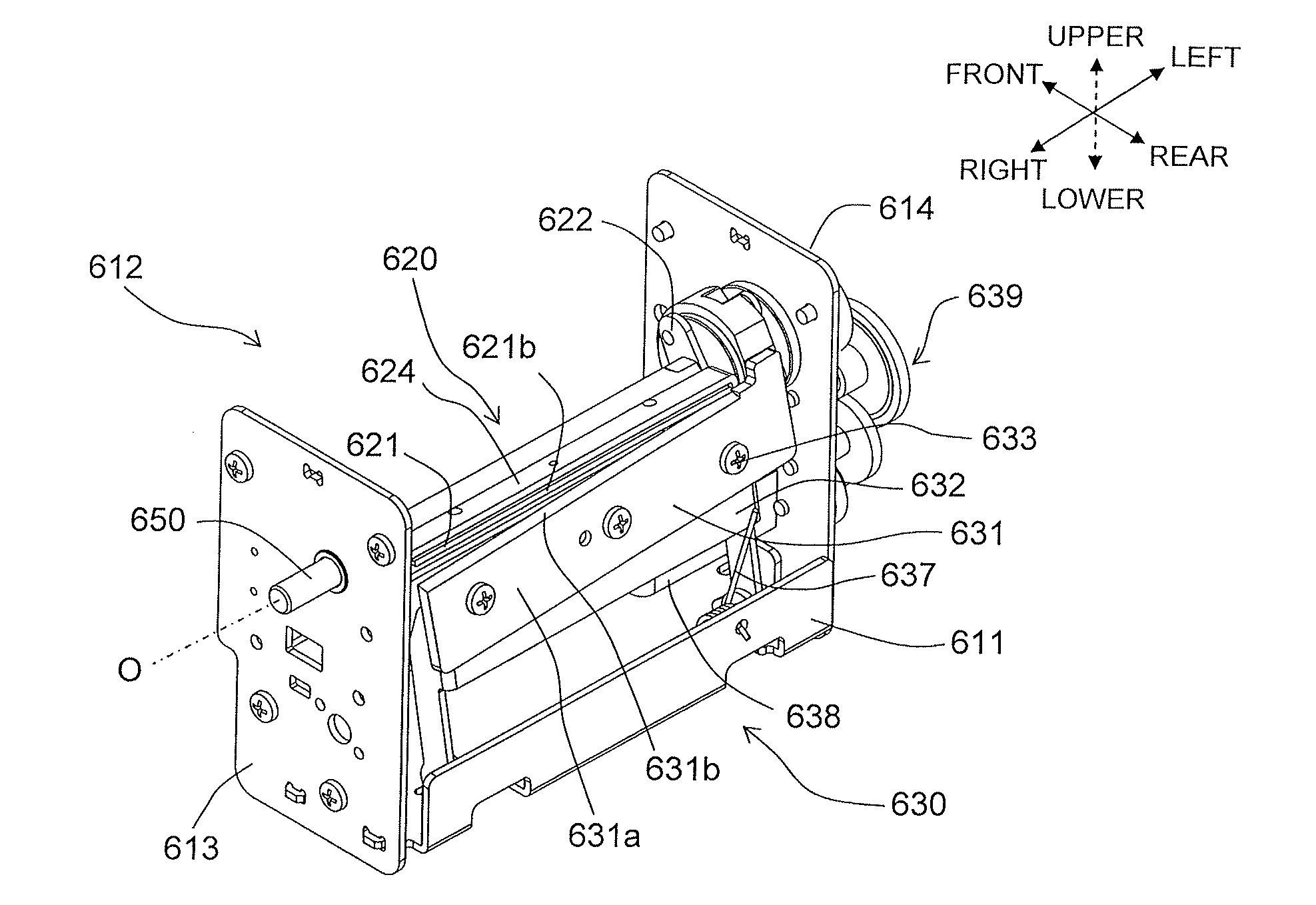
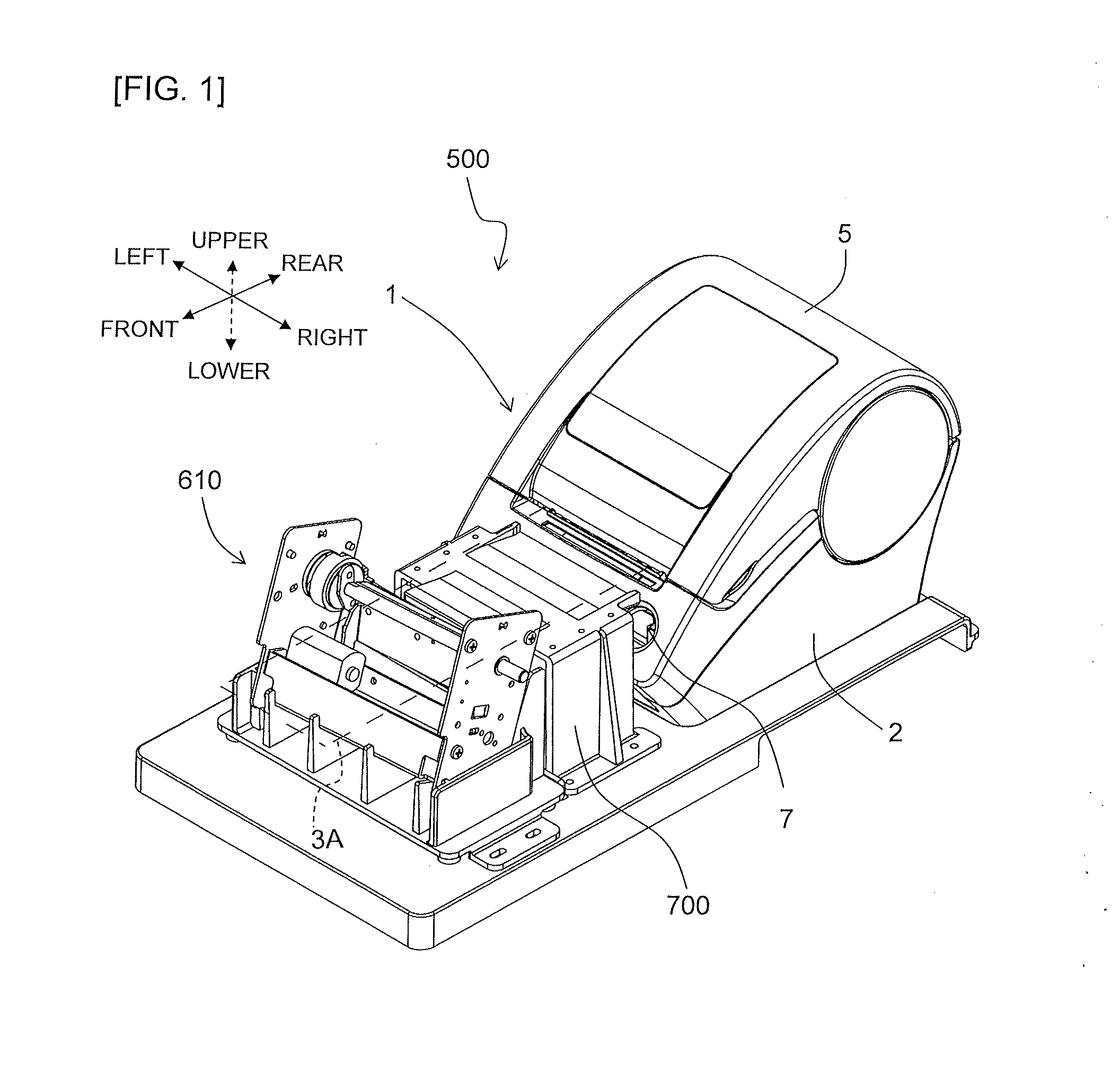
[0046]As illustrated in FIG. 1, the label producing apparatus 500 is provided with a label producing apparatus body 1 and a rotary cutter apparatus 610.

[0047]

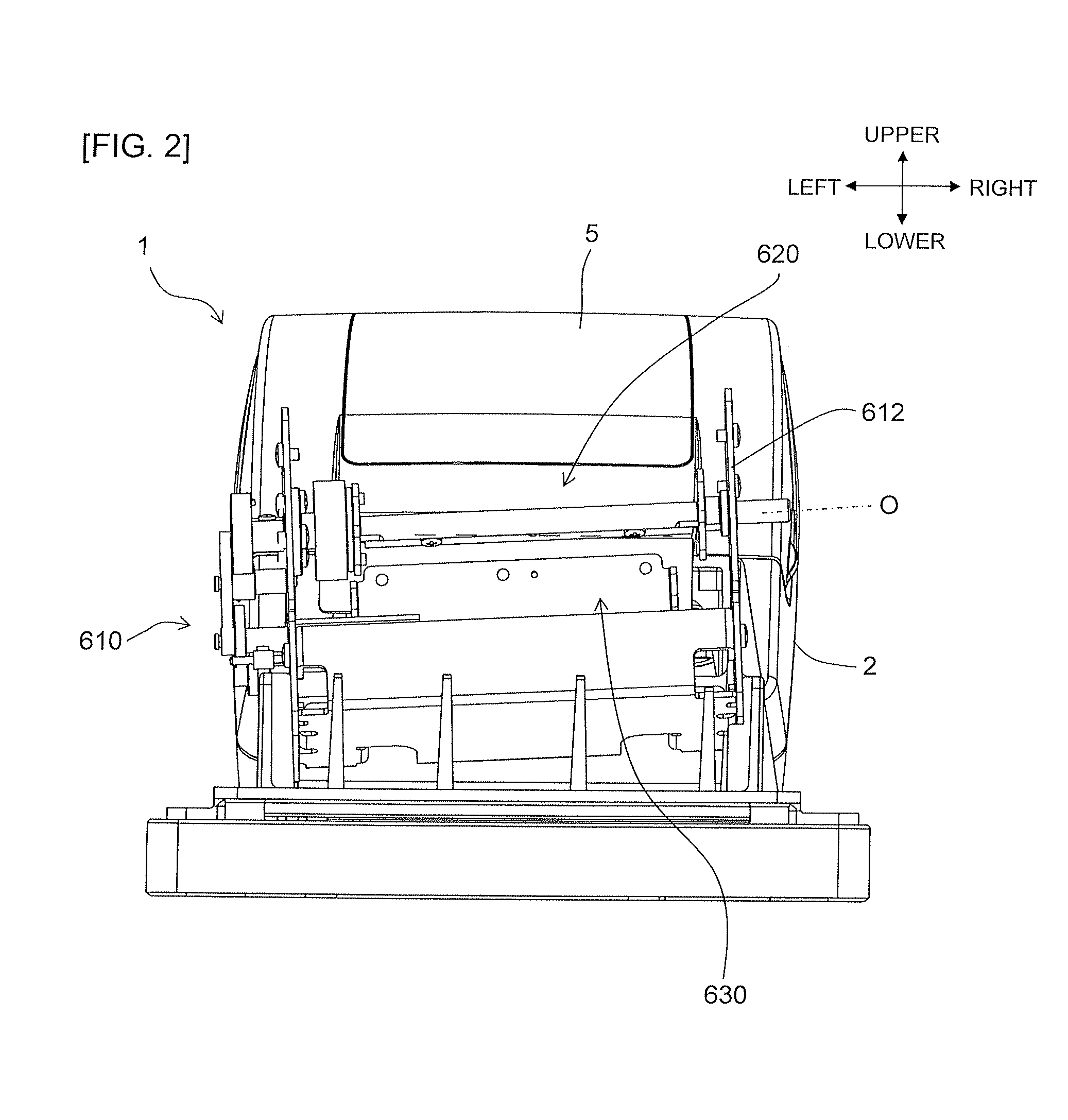
[0048]First, a configuration of the label producing apparatus body 1 will be explained by using FIGS. 1, 2, 3A, and 3B. The label producing apparatus body 1 includes a housing 2, an upper cover 5 made of a transparent resin, a power button 7 arranged on a front side of the housing 2, and the like.

[0049]As illustrated in FIG. 3B, a tape holder 3 is accommodated and arranged in a tape holder accommodating portion 4 arrang...


PUM


Abstract

A rotary cutter apparatus comprises a rotary body and a holding body. The rotary body is supported by a housing so as to rotate along a rotating direction. The holding body is supported by the housing. The rotary body has a rotary blade including a first edge portion. The holding body has a fixed blade including a second edge portion. The first edge portion is configured to be in contact with the second edge portion and to be rubbed with the second edge portion. The first edge portion and the second edge portion are configured to perform cutting of an object to be cut. The object is located in an introduction path. The rotary cutter apparatus further comprises a guide member configured to be in contact with the object and to guide it when the object is fed to an inside of a rotation trajectory of the rotary body.

Description

CROSS-REFERENCE TO RELATED APPLICATION[0001]This is a CIP application PCT / JP2012 / 067562, filed Jul. 10, 2012, which was not published under PCT article 21(2) in English.BACKGROUND[0002]1. Field[0003]The present disclosure relates to a rotary cutter apparatus for cutting an object to be cut and a printer using the rotary cutter apparatus.[0004]2. Description of the related Art[0005]A rotary cutter apparatus which can cut the object to be cut which is being fed without stopping the feeding is already known. In this prior-art rotary cutter apparatus, a spiral-shaped blade is provided on an outer periphery of a cylindrical body portion, and by making each part of the blade sequentially cut into the object to be cut, the object to be cut is cut linearly.[0006]In the aforementioned prior art, when the object to be cut is fed from a cutting position to the inside of a rotary body in an introduction path, means for guiding the object to be cut is not particularly provided. As a result, ther...

Claims


Application Information

Patent Timeline
Patent Type & Authority Applications(United States)
IPC IPC(8): B41J11/70
CPCB41J11/706B26D1/385B41J11/70B41J11/703
Inventor SAGO, AKIRAKATO, NOBUO
Owner BROTHER KOGYO KK
Why Eureka
Try Eureka