

Ball end mill
A technology of ball end mills and end mills, which is applied in the direction of milling cutters, milling cutting blades, milling machine equipment, etc., can solve difficult cutting processing and other problems, and achieve the effect of preventing chipping and defect and long-term stable cutting processing
- Summary
- Abstract
- Description
- Claims
- Application Information
AI Technical Summary
Problems solved by technology
Method used
Image

Examples
Embodiment 1、2
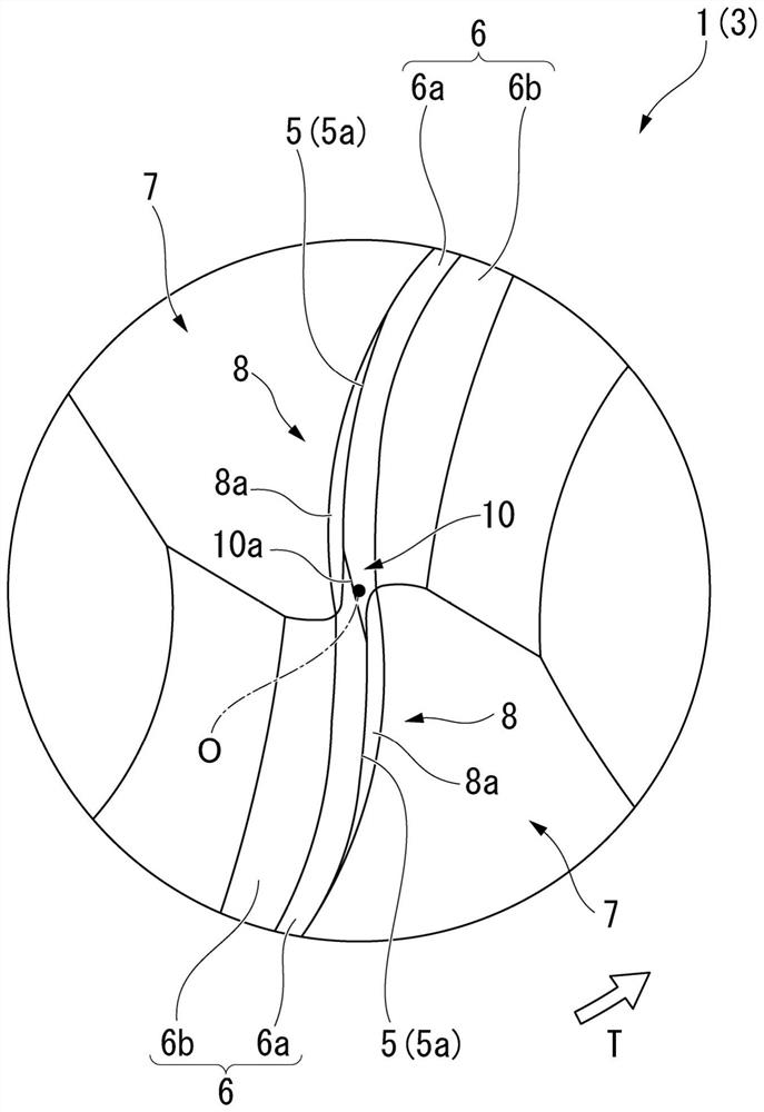
[0054] Next, an example of the present invention will be given, especially the ratio W / D of the width W (mm) to the diameter D (mm) of the chisel edge portion 10 in the present invention and the distance between the chip flutes 7 (center flutes 8 ) The effect of the ratio L / D of the staggered amount L (mm) to the diameter D (mm) is verified. In this example, the rake angle of the bottom edge 5a within the range where the chisel edge 10a is formed in the chisel edge portion 10 is -20 based on the above-described embodiment, the diameter D (mm) of the bottom edge 5a is 0.6 mm ° ball nose end mill, making a ball nose end mill with a ratio W / D of 0.023 and a ratio L / D of 0.075, and a ball nose end mill with a ratio W / D of 0.045 and a ratio L / D of 0.077 . These ball end mills were set as Examples 1 and 2 in this order.
Embodiment 3、4
[0056] In addition, for the ball nose end mill in which the diameter D (mm) of the bottom edge 5a is 0.6 mm based on the above-described embodiment, the leading edge of the bottom edge 5a within the range where the chisel edge 10a is formed in the chisel edge portion 10 is manufactured. The rake angle of the ball nose end mill with an angle of -25°, a ratio W / D of 0.040, and a ratio L / D of 0.052, and the bottom edge 5a within the range where the chisel edge 10a is formed in the chisel edge portion 10 is - 15° ball nose end mill with ratio W / D of 0.040 and ratio L / D of 0.052. These ball end mills were used as Examples 3 and 4 in this order. In addition, in the ball nose end mills of these Examples 1 to 4, the relief angle of the first flanking surface portion 6a was 6°, and the relief angle of the second flanking surface portion 6b was 14°.
Embodiment 5、6
[0068] Next, on the basis of the ball nose end mill of Example 1, a ball nose end mill having a relief angle of 3° on the first flank surface portion 6a and a ball having a relief angle of 9° on the first flank portion 6a were produced. head end mill. These ball end mills were used as Examples 5 and 6 in this order. In order to evaluate the machined surface roughness in finishing, cutting was performed for 60 minutes under the same conditions as the above-mentioned cutting conditions with the ball nose end mills of Examples 5 and 6 and the ball nose end mill of Example 1. , and measure the machined surface roughness of the bottom surface of the concave part of the workpiece at this time.
[0069] As a result, in the case of any of the ball end mills in Examples 1, 5, and 6, the machined surface roughness Rz (μm) of the workpiece after 60 minutes of machining was all about 0.3 μm. In the case of the ball nose end mill of Example 5 in which the relief angle of the first flank ...
PUM
| Property | Measurement | Unit |
|---|---|---|
| Diameter | aaaaa | aaaaa |
| Depth | aaaaa | aaaaa |
Abstract
Description
Claims
Application Information