Feeding device of a shearing machine

A technology of feeding device and shearing machine, which is applied in the direction of shearing device, shearing machine accessory device, metal processing equipment, etc., and can solve problems such as bar wear, poor transmission stability, and difficult to meet the requirements of bar product quality , to achieve the effect of improving service life and reducing failure

Inactive Publication Date: 2018-03-02
泉州鹏宜机械有限公司
View PDF7 Cites 0 Cited by
  • Summary
  • Abstract
  • Description
  • Claims
  • Application Information

AI Technical Summary

Problems solved by technology

After this structure is used for a long time, metal fatigue and wear will occur at the hinge point between the clamping oil cylinder and the movable clamping plate, and at the connection between the movable clamping plate and the clamping swing joint, which will affect accurate feeding.
[0005] 2. The piston rod of the feeding cylinder is fixed on the support, and the clamping cylinder and the fixed clamping plate are fixed on the feeding cylinder. In this way, the feeding cylinder bears the entire weight of the clamping cylinder, the fixed clamping plate and the processed bar, plus During the working process, the feeding cylinder moves back and forth repeatedly. After a long time of use, the oil cylinder is prone to oil leakage and poor transmission stability, which affects the service life of the feeding cylinder.
[0006] 3. When the feeding system is feeding, the bar is clamped by the movable clamping plate and the fixed clamping plate, and the bar is pushed to a station of the shearing system. When the feeding device of this structure pinches the bar, the bar The material often scrapes with the fixed blade of the shearing system, causing the wear of the bar. For some bars with high precision requirements, the wear marks of the bar will make the product quality difficult to meet the requirements.

Method used


Image

  • Feeding device of a shearing machine
  • Feeding device of a shearing machine
  • Feeding device of a shearing machine

Examples


Embodiment Construction

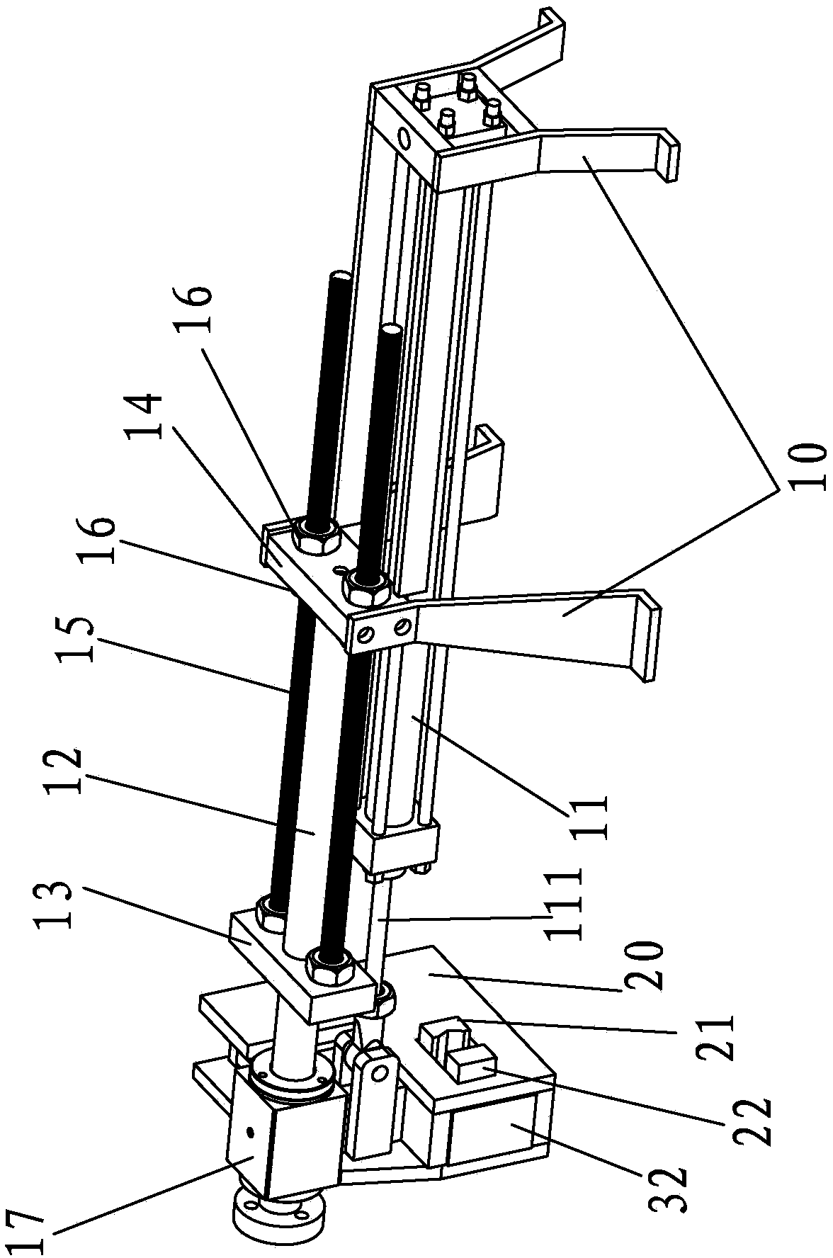
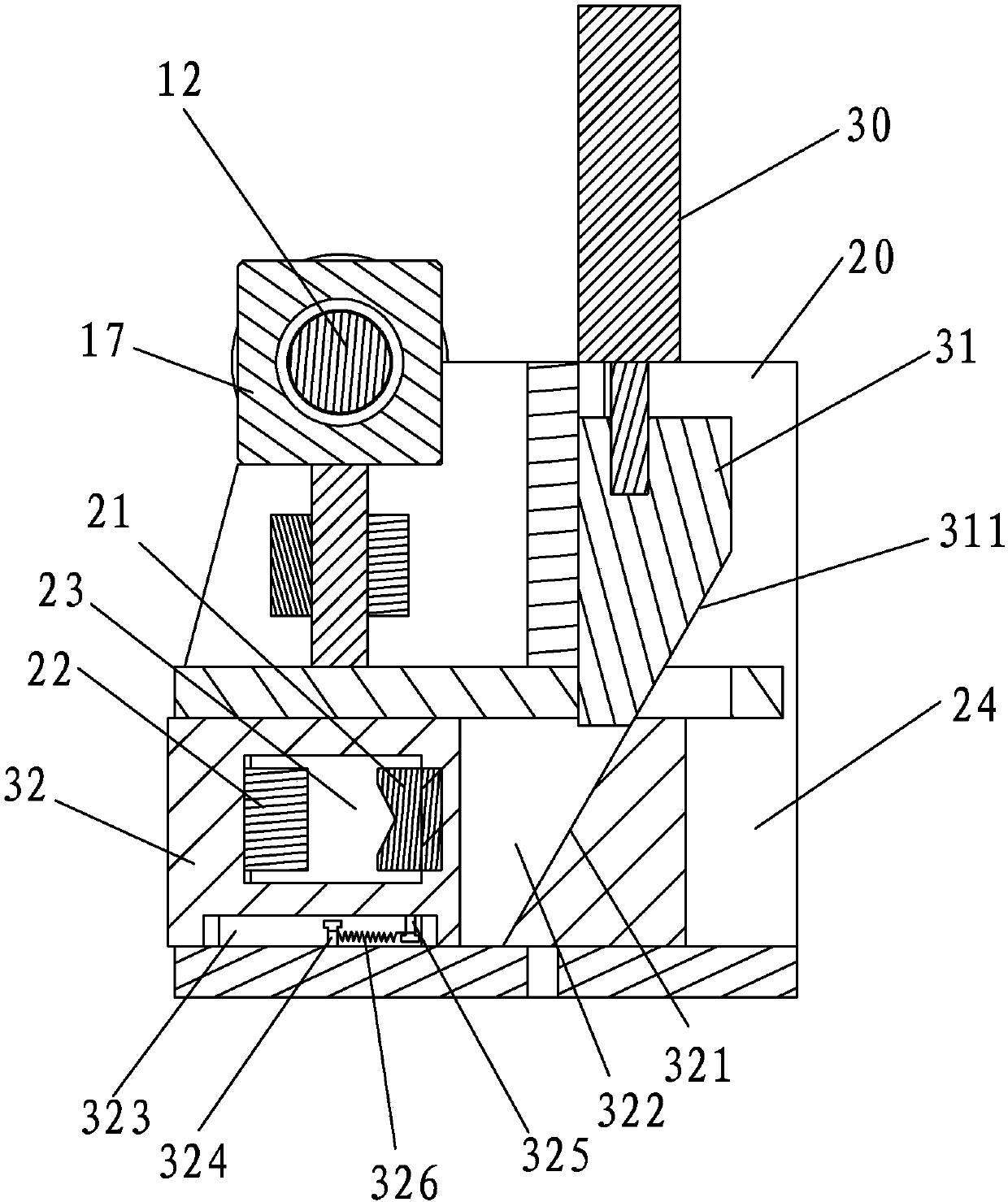
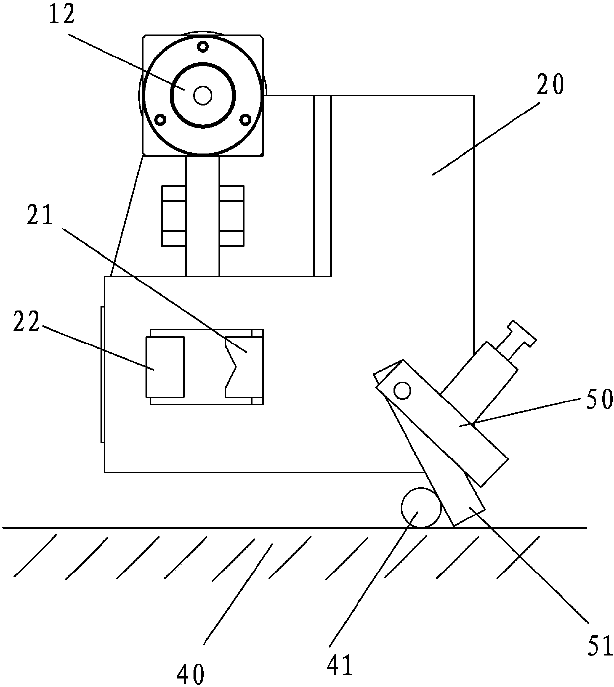
[0045] In order to further explain the technical solution of the present invention, the following will be described in detail in conjunction with the accompanying drawings.

[0046] refer to Figure 1 to Figure 4, the feeding device involved in the present invention is mainly used in shearing machines, such as in the Chinese utility model patent entitled "A Hydraulic Steel Bar Shearing Machine" with the authorized announcement number CN 203265493 U. The feeding device mainly realizes clamping and Feeding to ensure the continuous production of bar shearing. The feeding mechanism of the feeding device of the present invention includes a support 10 and a feeding cylinder 11 for driving the clamping mechanism to move back and forth, and the support 10 is fixed on the workbench 40 of the shearing machine. The feeding cylinder body 11 is connected on the support 10, and also includes a guide load-bearing rod 12, and the clamping mechanism is erected on the guide load-bearing rod 12...


PUM


Abstract

The invention relates to a feeding device of a shearing machine. The feeding device comprises a clamping mechanism for clamping a bar and a feeding mechanism for feeding the bar to a shearing system of the shearing machine. The feeding mechanism comprises a support and a feeding cylinder for driving the clamping mechanism to move back and forth. The feeding cylinder is connected to the support. The feeding device further comprises a guiding bearing bar. The clamping mechanism is erected on the guiding bearing bar in the mode of sliding relative to the guiding bearing bar. The clamping mechanism is improved, stable clamping is ensured, and meanwhile an adjusting device is added, so that bar conveying abrasion is avoided. The feeding device has the advantages of being simple in structure and capable of improving the product quality and prolonging the service life of a machine table.

Description

technical field [0001] The invention relates to a feeding device of a shearing machine. Background technique [0002] The production method of fasteners such as bolts and nuts is basically to cut the original specifications of the profiles and then process them into shape through the rest of the processing equipment. For example, the authorized announcement number CN 203265493 U, in the Chinese utility model patent titled "a hydraulic steel bar shearing machine", discloses a hydraulic steel bar shearing machine, including a frame, a motor, an oil pump, an oil tank, an oil circuit system, The shearing system, the motor is connected to the oil pump, and the oil pump transports the hydraulic oil in the oil tank to the oil circuit system, and the oil circuit system is connected to the shearing system. The hydraulic steel bar shearing machine also includes a feeding system, and the feeding system is arranged on the frame Above, the feeding system is connected with the oil system...

Claims


Application Information

Patent Timeline
Patent Type & Authority Patents(China)
IPC IPC(8): B23D33/02
CPCB23D33/02
Inventor 孙宜将
Owner 泉州鹏宜机械有限公司
Why Eureka
Try Eureka