Systems and methods for active component life management for gas turbine engines

a technology of active components and life management, which is applied in the direction of engines, machines/engines, mechanical equipment, etc., can solve the problems of reducing the overall efficiency of gas turbine engines, affecting the lifetime of components positioned along the hot gas path, and increasing the temperature of the turbine,

Inactive Publication Date: 2014-05-08
GENERAL ELECTRIC CO
View PDF7 Cites 31 Cited by
  • Summary
  • Abstract
  • Description
  • Claims
  • Application Information

AI Technical Summary

Benefits of technology

[0007]The present application and the resultant patent further provide an active cooling system for a compressor and a turbine of a gas turbine engine. The active cooling system may include one or more air extraction pipes extending from an intermediate stage of the compressor to a stage of the turbine, one or more heat exchangers positioned about the air extraction pipes, and an external air cooling system in communication with the air extraction pipes.

Problems solved by technology

Any air compressed in the compressor and not used in generating combustion gases, however, generally reduces the overall efficiency of the gas turbine engine.
Conversely, increased temperatures in the turbine may have an impact on emission levels and the lifetime of the components positioned along the hot gas path and elsewhere.
Given such, low load operations may be detrimental to the components in the aft stages while peak load operations may be detrimental to the components in all of the stages of the turbine.

Method used


Image

  • Systems and methods for active component life management for gas turbine engines
  • Systems and methods for active component life management for gas turbine engines
  • Systems and methods for active component life management for gas turbine engines

Examples


Embodiment Construction

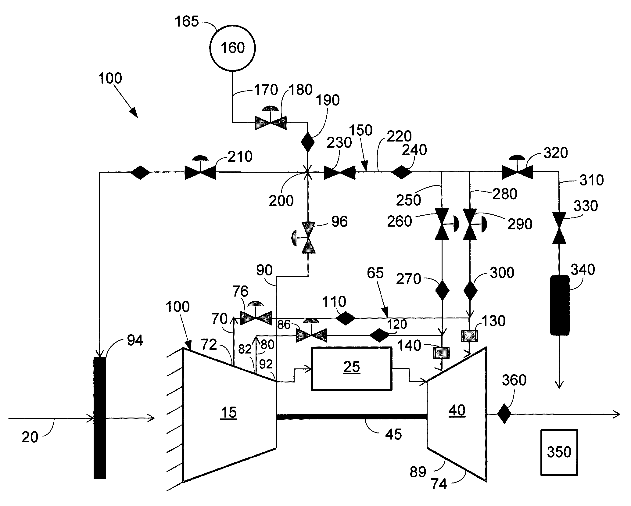
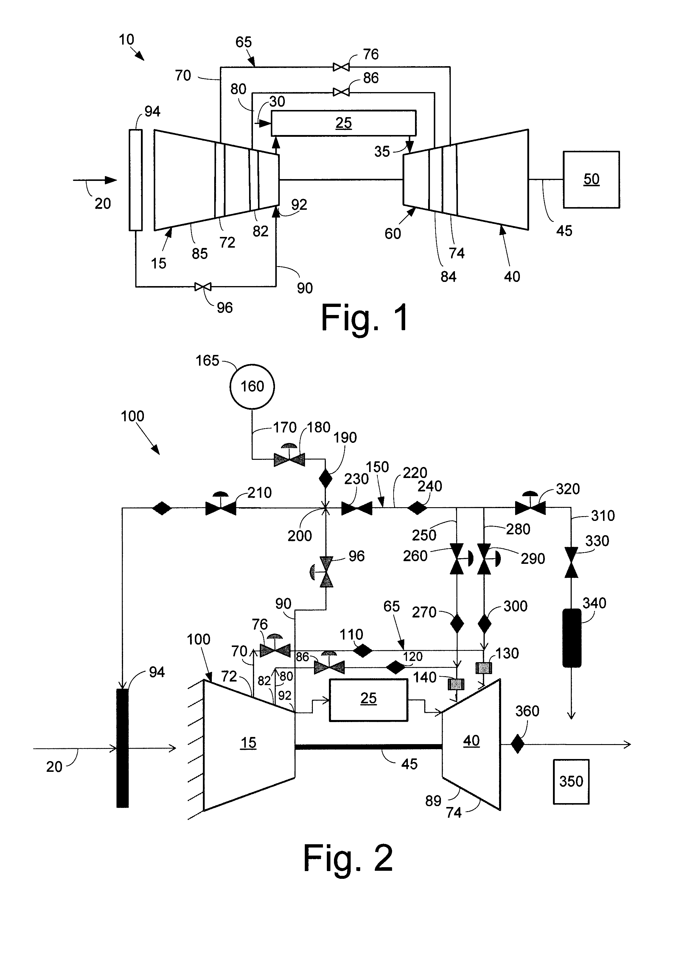
[0013]Referring now to the drawings, in which like numerals refer to like elements throughout the several views, FIG. 1 shows a schematic view of gas turbine engine 10 as may be used herein. The gas turbine engine 10 may include a compressor 15. The compressor 15 compresses an incoming flow of air 20. The compressor 15 delivers the compressed flow of air 20 to a combustor 25. The combustor 25 mixes the compressed flow of air 20 with a pressurized flow of fuel 30 and ignites the mixture to create a flow of combustion gases 35. Although only a single combustor 25 is shown, the gas turbine engine 10 may include any number of combustors 25. The flow of combustion gases 35 is in turn delivered to a turbine 40. The flow of combustion gases 35 drives the turbine 40 so as to produce mechanical work. The mechanical work produced in the turbine 40 drives the compressor 15 via a shaft 45 and an external load 50 such as an electrical generator and the like.

[0014]The gas turbine engine 10 may us...


PUM


Abstract

The present application thus provides an active cooling system for a compressor and a turbine of a gas turbine engine. The active cooling system may include an air extraction pipe extending from the compressor to the turbine, a heat exchanger positioned about the air extraction pipe, and an external air cooling system in communication with the air extraction pipe.

Description

TECHNICAL FIELD[0001]The present application and the resultant patent relate generally to gas turbine engines and more particularly relate to active component life management systems and methods to provide additional cooling to compensate for peak, low, and ultra-low load operations and other types of operational parameters.BACKGROUND OF THE INVENTION[0002]Gas turbine engines generally use bleed air from one or more stages of a compressor to provide cooling and / or sealing of the components along the hot gas path within the turbine. Air may be extracted from the compressor and routed externally or internally to the locations that require cooling in the turbine, defined herein as a turbine cooling circuit. Any air compressed in the compressor and not used in generating combustion gases, however, generally reduces the overall efficiency of the gas turbine engine. Conversely, increased temperatures in the turbine may have an impact on emission levels and the lifetime of the components p...

Claims


Application Information

Patent Timeline
Patent Type & Authority Applications(United States)
IPC IPC(8): F01D25/12
CPCF01D25/12F02C7/143F02C7/18
Inventor EKANAYAKE, SANJISMITH, RAUB WARFIELDSCIPIO, ALSTON ILFORDHARTMAN, STEVENHOSKIN, ROBERT FRANK
Owner GENERAL ELECTRIC CO
Why Eureka
Try Eureka