Electrical connection terminal

a technology of electric connection and terminal, which is applied in the direction of coupling device connection, coupling device details, coupling/disassembly parts, etc., can solve the problems of special double spring, complex installation of double spring which has been inserted into the clamping frame, and the mounting of the clamping frame with the current bar molded on i

Inactive Publication Date: 2014-05-08
PHOENIX CONTACT GMBH & CO KG
View PDF3 Cites 83 Cited by
  • Summary
  • Abstract
  • Description
  • Claims
  • Application Information

AI Technical Summary

Benefits of technology

[0009]Therefore, the object of the invention is to develop an electrical connection terminal as described initially such that it has a structure that is as simple as possible, and a connection of rigid conductors or conductors provided with a wire end ferrule is to be directly possible, i.e., without the clamping site having to be opened beforehand with a tool. Moreover, the maximum cross section of the conductor to be connected is to be independent of whether the conductor has a wire end ferrule or not.

Problems solved by technology

However, the disadvantage here is that a special double spring is needed as the clamping spring.
Moreover, the mounting of the clamping frame with the current bar molded on it and of the double spring which has been inserted into the clamping frame is complex.

Method used


Image

  • Electrical connection terminal
  • Electrical connection terminal
  • Electrical connection terminal

Examples


Embodiment Construction

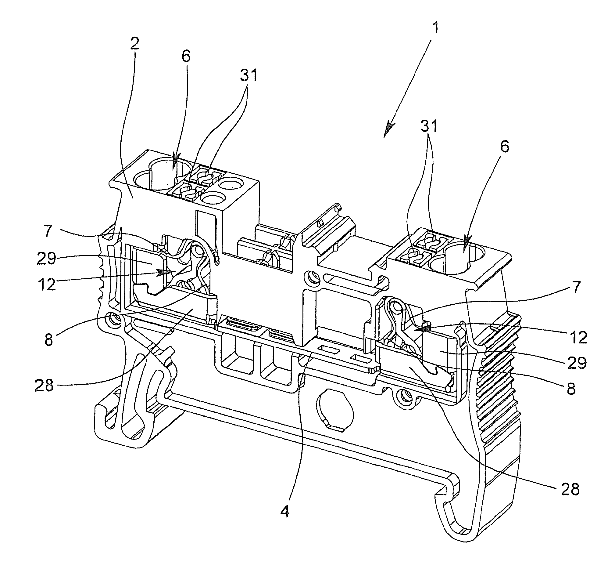
[0034]FIG. 1 shows an electrical connection terminal 1 which is made as a terminal block. The electrical connection terminal 1 has a plastic housing 2, there being two clamping springs 3, 3′ (see, FIG. 4) and one current bar 4 which connects the clamping springs 3, 3′ to one another in the housing 2 on each of the two sides of the electrical connection terminal 1. To accommodate the clamping springs 3, 3′ and at least the two ends of the current bar 4, two chambers 5 are made in the housing 2 of the terminal block (see, FIG. 4). The conductors to be connected can each be inserted into one chamber 5 via a conductor entry opening 6 into which two electrical conductors can be inserted. Fundamentally, instead of the illustrated “double” conductor entry opening 6 two individual conductor insertion openings can also be made next to one another, and then, only one conductor can be inserted into each conductor insertion opening. As FIG. 1 shows, the clamping springs 3, 3′ which are accommod...


PUM

PropertyMeasurementUnit
spring forceaaaaaaaaaa
electricalaaaaaaaaaa
densityaaaaaaaaaa

Abstract

An electrical connection terminal having a housing, two clamping springs and a current bar, wherein a chamber is formed in the housing for receiving the clamping springs and at least one end of the current bar as well as a conductor insertion opening for inserting two conductors, and wherein the clamping springs are arranged next to each other in relation to the longitudinal extension of the current bar. In the electrical connection terminal, the clamping springs each have a clamping leg, an operating leg and a back which connects the two legs to one another, wherein the clamping limbs, together with the current bar form, in each case, a clamping point for a stripped conductor that is to be connected. Moreover, a spring receptacle is provided within the chamber, which has a partition, the two clamping springs being disposed on a respective side of the partition.

Description

BACKGROUND OF THE INVENTION[0001]1. Field of the Invention[0002]The invention relates to an electrical connection terminal with a housing, with two clamping springs and with at least one current bar, the housing having a chamber for accommodation of the clamping springs and at least one end of the at least one current bar and at least one conductor entry opening for entry of two conductors, and the clamping springs being located next to one another relative to the longitudinal extension of the current bar. In addition, the invention also relates to a method for mounting of a corresponding electrical connection terminal.[0003]2. Description of Related Art[0004]Electrical connection terminals are known in a plurality of embodiments. The terminals can be made, for example, for connection to another conductor as a terminal block or for connection of an electrical conductor to a circuit board as a so-called print terminal. Moreover, electrical connection terminals can also be part of ele...

Claims


Application Information

Patent Timeline
Patent Type & Authority Applications(United States)
IPC IPC(8): H01R13/627H01R43/20
CPCH01R43/20H01R13/627H01R9/26Y10T29/49208H01R4/48275
Inventor HOPPMANN, RALPHSTRATO, MICHAEL
Owner PHOENIX CONTACT GMBH & CO KG
Why Eureka
Try Eureka